


14
DATE OF ISSUE: December 2001
Jaguar X-TYPE 2.0L/2.5L/3.0L
Symbols and Codes
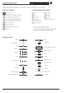
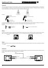
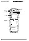
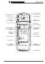
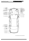
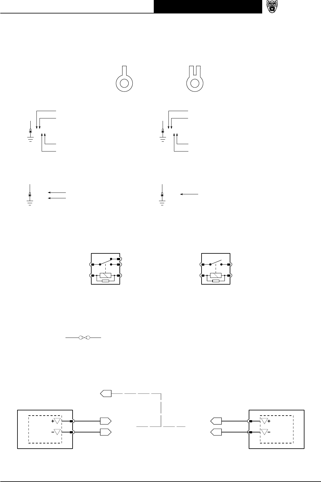
Grounds
There may be up to three eyelets on one ground stud. A, B and C are used to indicate the position of the eyelet on the stud: A – first (bottom),
B – second (middle), C – third (top). Two eyelet variations are used: a single eyelet and an eyelet pair. The single eyelet has a single ‘leg’,
which is identified by an S; the eyelet pair has two ‘legs’, identified as L (left) or R (right).
EXAMPLE:
SLR
SINGLE EYELET EYELET PAIR
G15AS G30CR
Ground
Ground stud number 15
Single eyelet
First eyelet on stud
Ground
Ground stud number 30
Eyelet pair, RH leg
Third eyelet on stud
On figures where LHD and RHD circuits are combined and the ground designation differs from LHD to RHD, the RHD ground is shown in
parentheses. If the ground designation is the same for LHD and RHD, only one ground designation is used.
EXAMPLE:
G15AR
(G4AR)
G30AS
LHD Vehicles
RHD Vehicles
Same for LHD and RHD Vehicles
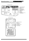
Relays
All relays are located in the Power Distribution Fuse Box and the Central Junction Fuse Box. Relays do not have a separate relay connector
(base). All relays use the ISO pin numbering system (1, 2, 3, 4, 5). Each relay in the vehicle is identified by a unique “R” number.
EXAMPLE:
3
1
5
2
R6
4
3
1
5
2
R2
CHANGE-OVER RELAY NORMALLY OPEN RELAY
Fuses
All fuses are located in the Power Distribution Fuse Box and the Central Junction Fuse Box. Each fuse in the vehicle is identified by a unique
“F” number.
EXAMPLE:
F67 30A
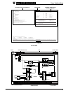
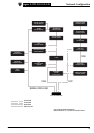
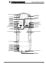
Networks
In most instances, networks are shown as a broken grey line to indicate that there is network communication between the depicted control
modules. Refer to Figures 20.1, 20.2, 20.3 and 20.4 for circuit details.
EXAMPLE:
S
S
IP5-2
IP5-1
20.2
20.2 20.2
IP10-1
IP10-2
S
S
U
Y
U
Y
20.2
SCP
MESSAGE(S)
MESSAGE(S)
MESSAGE(S)
MESSAGE(S)
CONTROL MODULE CONTROL MODULE