


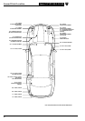
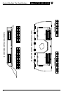
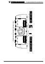
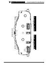
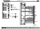
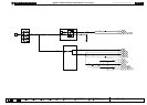
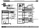

Refer to the front of this book for detailed information and illustrations regarding the location and identification of harnesses, relays, fuses, grounds, control
modules and control module pins.
DATE OF ISSUE: December 2001
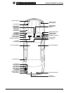
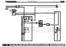
Fig. 01.1
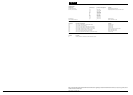
COMPONENTS
Component Connector(s) Connector Description Location
BATTERY —— ENGINE COMPARTMENT
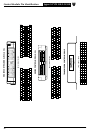
CENTRAL JUNCTION FUSE BOX CA75 8-WAY / GREY PASSENGER COMPARTMENT, FRONT BULKHEAD LH SIDE
CA76 16-WAY / GREEN
CA77 2-WAY / GREY
CA78 16-WAY / GREY
IP1 14-WAY / GREEN
IP2 16-WAY GREY
IP3 2-WAY / GREY
IP4 14-WAY / GREY
JB50 4-WAY / GREY
JB51 16-WAY / BLUE
JB52 2-WAY / BLACK
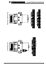
IGNITION SWITCH IP18 7-WAY / BLACK STEERING COLUMN
INERTIA SWITCH IP132 3-WAY / BLACK LOWER RH A POST
POWER DISTRIBUTION FUSE BOX —— ENGINE COMPARTMENT LH SIDE
TRANSIT ISOLATION DEVICE JB186 2-WAY / BLACK BATTERY
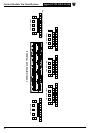
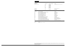
HARNESS IN-LINE CONNECTORS
Connector Connector Description Location
JB3 14-WAY / BLUE / JUNCTION BOX HARNESS TO INSTRUMENT PANEL HARNESS BELOW INSTRUMENT PANEL LH SIDE
JB130 22-WAY / GREEN / JUNCTION BOX HARNESS TO INSTRUMENT PANEL HARNESS ADJACENT TO CENTRAL JUNCTION FUSE BOX
GROUNDS
Ground Location
G13 ENGINE COMPARTMENT / UNDER BATTERY TRAY
G16 ENGINE COMPARTMENT / ENGINE BLOCK