


Establishing an HA Connection Between Devices
NetScreen-200 Series 21
To cable two NetScreen-200 Series devices together for HA and connect them to the
network:
1. (Optional) Install the NetScreen-200 Series devices in an equipment rack (see
“Equipment Rack Installation Guidelines” on page 10).
2. Make sure that all ON/OFF power supply switches are OFF.
3. Connect the power cables to each NetScreen-200 power supply then connect
them to a power source.
4. If your device is a NetScreen-204, connect a 10/100 Base-T cable from the
ethernet4 on Device 1 to the ethernet4 port on Device 2.
or
If your device is a NetScreen-208, connect a 10/100 Base-T cable from the
ethernet8 on Device 1 to the ethernet8 port on Device 2.
Device 1
5. On Device 1, connect a 10/100 Base-T cable from ethernet1 to the switch
labeled “Switch 3.”
6. On Device 1, connect a 10/100 Base-T cable from ethernet2 to the switch
labeled “DMZ.”
7. On Device 1, connect a 10/100 Base-T cable from ethernet3 to the switch
labeled “Layer 3 switch 1.”
Device 2
8. On Device 2, connect a 10/100 Base-T cable from ethernet1 to the switch
labeled “Switch 4.”
9. On Device 2, connect a 10/100 Base-T cable from ethernet2 to the switch
labeled “DMZ.”
10. On Device 2, connect a 10/100 Base-T cable from ethernet3 to the switch
labeled “Layer 3 switch 2.”
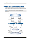
Note: The cabling instructions given below reproduce the configuration shown previously.
However, this is not the only possible HA configuration. In addition, the instructions
assume that all physical ports and interfaces are set at their default settings. If you have
changed the port and interface configurations, the instructions below might not work
properly.
Note: Whenever you deploy two NetScreen-200 Series devices in an HA cluster,
connect each to a different power source, if possible. If one power source fails, the
other source might still be operative.