


Chapter 3 Configuring the Device
22 User’s Guide
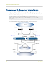
Switches
11. Cable together the switches labeled “Switch 3” and “Switch 4.”
12. Cable together the switches labeled “Layer 3 switch 1” and “Layer 3 switch 2.”
13. Cable the switches labeled “Layer 3 switch 1” and “Layer 3 switch 2” to routers.
14. Turn the power switches for all devices ON.
For more advanced HA configurations, see the NetScreen Concepts & Examples ScreenOS
Reference Guide.
PERFORMING INITIAL CONNECTION AND CONFIGURATION
To establish the first console session with the NetScreen-200 Series device, use a vt100
terminal emulator program through the provided RJ-45/DB9 serial port connector.
Establishing a Terminal Emulator Connection
To establish an initial console session:
1. Plug the DB9 end of the supplied RJ-45/DB-9 serial cable into the serial port of
your computer. (Be sure that the DB-9 is seated properly by screwing in the
thumbscrews.)
2. Plug the RJ-45 end of the cable into the Console port of the NetScreen-200 Series
device. (Be sure that the RJ-45 clip snaps into the port and is seated properly.)
3. Launch a Command Line Interface (CLI) session between your computer and
the NetScreen-200 device using a standard serial terminal emulation program
such as Hilgraeve Hyperterminal (provided with your Windows operating
system). The settings should be as follows:
• Baud Rate to 9600
• Parity to No
• Data Bits to 8
• Stop Bit to 1
• Flow Control to none
4. Press the ENTER key to see the login prompt.
5. At the login prompt, type netscreen.
Note: The switch ports must be defined as 802.1Q trunk ports, and the external
routers must be able to use either Hot Standby Router Protocol (HSRP) or
Virtual Router Redundancy Protocol (VRRP). For the best configuration method,
see the documentation for your switch or router.