


Chapter 2—Functional Descriptions
Model 330, 340SC and 370SC Service Manual 2–1
2.0 Functional Descriptions
Contents
2.1 Cover and Base............................................................................................2–2
2.2 External Power Requirements.....................................................................2–3
2.3 Electronics Systems Overview....................................................................2–3
2.4 System Power..............................................................................................2–5
System Power Supply................................................................................2–5
Arc Lamp Ignitor.......................................................................................2–9
High Voltage Power Supply......................................................................2-11
2.5 Card Cage....................................................................................................2-14
2.6 Circuit Boards .............................................................................................2-15
Raster Timing Generator Board (RTG) p/n 100568 ................................2-18
Horizontal Deflection Board P/N 102523 (HDB).....................................2-25
Vertical Deflection Board P/N 102521(VDB) ..........................................2-32
Video Processor Board P/N 104672 (VPB) ..............................................2-43
Video Amplifier Board P/N 103567 or 103774 (VAB)............................2-54
System Controller Board P/N 104668 (SCB)............................................2-59
Backplane Board p/n 100571 ...................................................................2-71
2.7 Optical Section ............................................................................................2-72
CRT Assembly ..........................................................................................2-72
Arc Lamp Assembly..................................................................................2-75
Optical Subassemblies...............................................................................2-76
2.8 Image Light Amplifier.................................................................................2-76
This chapter provides functional descriptions of the major assemblies in the
Model 330, 340SC and 370SC projectors.
Emphasis is placed on a description of system components to the functional block
level. A number of block diagrams are provided for user reference.
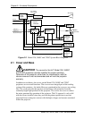
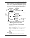
Figure 2-1 provides a block diagram overview of the HJT Model 330, 340SC and
370SC projectors. For simplicity, each major electronics assembly is shown with
signal paths between appropriate functional units. Major physical and electronics
assemblies will be described in more detail in the following sections of this
chapter.