Chapter 2—Functional Description
Model 330, 340SC and 370SC Service Manual 2-45
further use in the Video Processor Board. The IIC bus is used by the decoder to
select either Channel 3 (NTSC) or Channel 4 (S-Vid). The two (2) signals are
multiplexed together on the decoder board for export to the Video/Sync Mux.
Video/Sync Mux
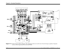
The Video/Sync Mux selects one (1) of three (3) external inputs (RGB1, RGB2,
or Decoder) for use as the source for Image display and sync signals. The two (2)
external RGB Sync signals are selected by choosing RGB1 or RGB2 in the
C
HANNEL
L
IST
under the C
HANNEL
M
ENU
. Selecting either CVID (for the
composite input) or SVHS (for the S-Vid input) from the same C
HANNEL
L
IST
uses the input from the decoder. The input to be used is selected by the System
Controller Board via the IIC bus. A green LED on the input panel is lit to indicate
which input is selected. The RGB image inputs are AC coupled while the sync
and decoder inputs are DC coupled. All inputs have a 75 ohm input impedance.
V & H Sync Strip
The vertical and horizontal sync signals are taken from the Video/Sync Mux and
individually peak and trough detected then pulse shaped to provide a TTL-level
signal representing the HSYNC and the VSYNC. Those signals are then sent out
to the RTG as the signals HSYNC and VSYNC and can be monitored on TP 14
and 15 respectively.
SG Sync Strip
The SG Sync Strip circuit looks at the green image signal between the video
MUX and the Brightness and Contrast Amp and sends the signal through a buffer
then peak detects the signal. The peak-detected signal then is compared with a
reference voltage to discriminate the sync signal from the video. The stripped sync
signal is then pulse shaped to provide a TTL representation of the composite sync
signal. The signal is sent out to the RTG as SGSYNC and can be probed at TP 13.
B, G, and R Brightness and Contrast Amplifiers
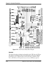
Each color of video (R, G, and B) uses an identical circuit. The Brightness and
Contrast amplifier serves to adjust the black and white levels of the external video
and also protects the CRT from excessive beam current by taking the beam
current signal from the Video Output Amp and comparing it with a reference. If
the beam current exceeds 1mA, the contrast command voltage is reduced to a
level that brings the CRT beam current back within bounds.
The Brightness and Contrast amplifier takes the contrast command signal after the
beam current limit circuit, and uses it to set the gain of the amplifier for contrast
control. Contrast is controlled by the SCB via the IIC interface. The operator
controls contrast level by pressing the C
ONT
button and using the up and down
arrows on the remote control. Green is a master and will control all three (3)
colors together. R and B are independent.


