


Chapter 3---Service Adjustments
3-4 Model 330, 340SC, 370SC Service Manual
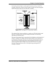
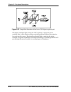
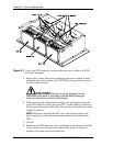
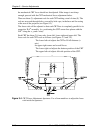
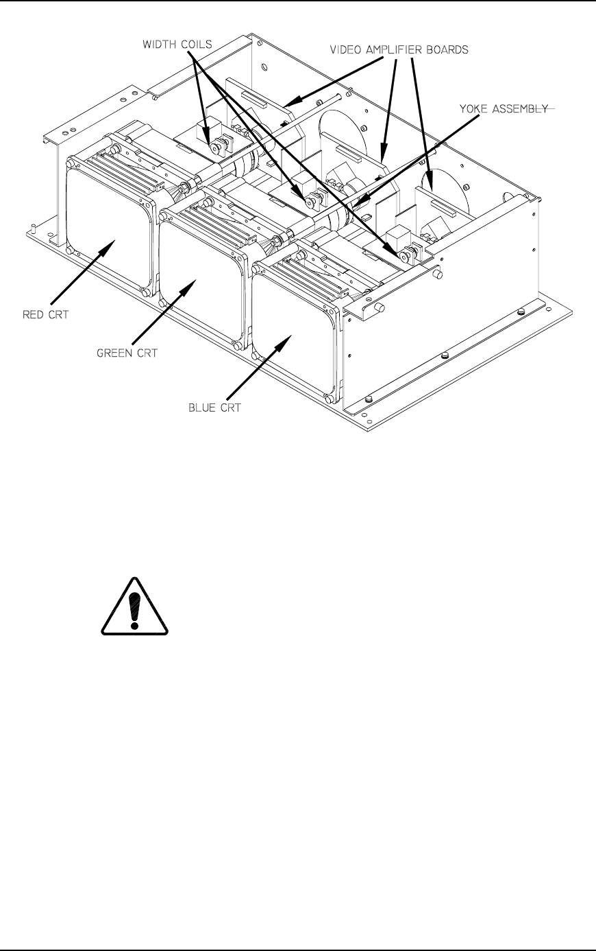
Figure 3-2
View of the CRT Assembly showing deflection yokes, width coils, CRTs
and Video Amplifiers.
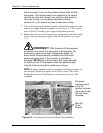
5. Remove the 2.5mm Allen screw holding the electronics module in place
and tilt the electronics module (see CAUTION following) back to expose
the CRT necks and yoke.
CAUTION!
Remove anything plugged into the
rear electronics jacks or the plugs could be badly damaged
when the electronics module is tilted back.
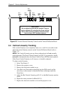
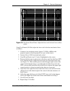
6. While observing the center horizontal line on the grid pattern, rotate the
green CRT deflection yoke, (the green CRT is in the middle), to achieve a
level image at the center of the screen (if necessary, loosen the yoke clamp
slightly to adjust it).
NOTE:
Whenever adjusting the CRT yoke, push forward on the yoke
while rotating it to ensure the yoke remains properly positioned on the
CRT.
7. View R.
8. Rotate the red CRT deflection yoke (on the right of the projector–from the
rear) to achieve a level image at the center of the screen (it should be
parallel to the green central horizontal line).