


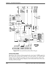

Chapter 2—Functional Descriptions
2-22 Model 330. 340SC, and 370SC Service Manual
method as the /CORSTRT signal but has a separate command from the SCB. It controls
the timing of the top and bottom pincushion correction, top and bottom keystone
correction, and horizontal linearity correction. The signal timing is selected by the user
and controlled by the SCB. Adjusting P
INCUSHION
P
OSN
under the T
IMING
S
ETUP
M
ENU
controls it.
Vertical phase adjustment is accomplished by timing the /VFBST (vertical start) signal
with respect to the regenerated vertical sync signal. This signal is generated by counting a
commanded number of horizontal lines after the vertical sync signal /VSYNCSC. The
signal timing is selected by the user and controlled by the SCB. It is controlled by
adjusting PHASE using the up/down arrows.
DC restore timing determines the point in time that the signal is clamped and the DC
restore (Section 2.6.4, Video Processor Board) function is accomplished. The user has
three (3) choices from which the DC restore timing can be selected. These are Backporch
(BP), Tri-level (TL), and Sync-tip (ST). The choices are selected in the SL column of the
C
HANNEL
L
IST
under the C
HANNEL
M
ENU
(Figure 5-1, Menu Structure).
The DC restore timing counts a preset number of Hx224 clock pulses after the HSYNC
signal leading edge. ST will clamp and DC restore during the time that the HSYNC pulse
is active. ST clamping is timed with respect to the leading edge of the HSYNC pulse. It is
seldom used but is necessary when there is no back porch to clamp on (image starts
immediately after the sync pulse). BP will clamp and DC restore shortly after the HSYNC
pulse. BP clamping is timed with respect to the trailing edge of the HSYNC pulse. The
timing is calculated to be on the back porch of the signal (after the sync pulse but before
the image begins). This is the most frequently used clamp timing.
The default setting for the DC restore timing is BP when a new channel is set up. TL
clamping occurs significantly after the HSYNC pulse. The purpose of TL timing is to
provide DC restore timing that is compatible with the Tri-level type sync used with
HDTV signals. Like BP, TL clamping is timed with respect to the trailing edge of the
HSYNC pulse. The output of the Synctip/Backporch circuit is a pulse signal (DCRSTR)
going to the VPB.
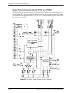
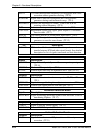
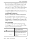
Serial Communication
The RTG uses only the IIC bus for serial communication with the SCB (Section 2.6.6).
The information transferred over the IIC bus is indicated below (I = input to RTG, O =
output from RTG). A change in output data generates an interrupt pulse.
Table 2-4
IIC BUS Information
I/O
Information
Description
I
Priority Select
Commanded sync selection priority
(always fixed as described above).
I
Vertical Flyback Start Delay
Commanded V phase.
I
Map Start Delay
Commanded timing for vertical positioning
of correction map.
I
L Blank
Commanded position of left blanking.
I
R Blank
Commanded position of right blanking.