


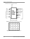

Chapter 2—Functional Descriptions
2-20 Model 330. 340SC, and 370SC Service Manual
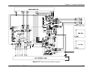
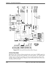
Serration and Equalization Lockout
The Serration and Equalization Lockout takes a composite sync signal and removes any
equalization and serration pulses from it. The Model 330, 340SC and 370SC projectors
do not require these pulses to operate. Removal of the serration and equalization pulses
provides a faster, more reliable response to the vertical sync and subsequent relock to
horizontal sync. This circuit uses the 4xHsync clock that is generated in the PLL to delete
any sync information present in the center portion of the incoming horizontal waveform.
Phase Locked Loop
The PLL receives horizontal sync stripped of the serration and equalization pulses from
the Serration and Equalization Lockout circuit.
The Horizontal Sync signal is fed to horizontal frequency decoder which uses a
frequency/voltage circuit to pre-tune the VCO of the PLL to ensure proper locking. The
Horizontal Frequency Decoder also provides a count of the number of horizontal lines per
frame. The H count is then sent via the IIC interface, to the SCB (HCOUNT). The SCB
uses this information to set up the correction and overlay maps and to calculate the H
frequency.
The PLL takes in the horizontal sync signal and generates a clock signal that is a square
wave of 224 times the horizontal frequency. The PLL will perform this function over the
entire range of horizontal frequencies, 15KHz to 90Khz. It will maintain that signal over
the full period of the raster including the vertical sync pulse. Counters in the PLL circuit
also provide clock signals with frequencies of Hx112, Hx4, Hx2, and Hx1. These clock
signals are square wave signals and are phase-coherent with respect to the H sync signal.
The Hx224, Hx112, and Hx1 signals are used on both the RTG and the SCB for timing of
corrections and raster adjustment. The signals that go to the SCB are Hx224, Hx112
(clock signals), and /HSYNCR (regenerated HSync, a negative-going pulse signal that is
timed to be on the leading edge of the Hx1 clock). The Hx4 and Hx2 clocks are used
exclusively on board the RTG for sync detection and timing.
Control of phase noise is critical—jitter will translate into a "smearing" of the projected
image. Therefore, if the PLL loses lock, the /Phase Lock signal is sent to the SCB via the
IIC interface. The SCB then makes a decision based on that information.
VSYNC Detector, Field Separator, and Mux
The VSync detector uses the Hx2 clock signal to detect the vertical sync signal from the
composite external sync signal that arrives on either the HSYNC input or the sync-on-
green input.
The field separator determines whether or not the signal is interlaced and, if so, which
field is currently being displayed. This information is sent to the SCB as the signals INTI
(interlace indication, high if interlaced), /FIELD1 (low when the field number 1 is
current), and /FRAMEST (indicates the beginning of a new frame).
The mux takes the external Vsync and field signals and multiplexes them with the
internal sync signal to select which will be used. The multiplexed Vsync signal is pulse-