


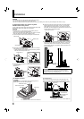
10
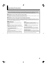
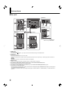
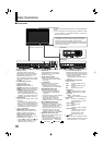
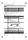
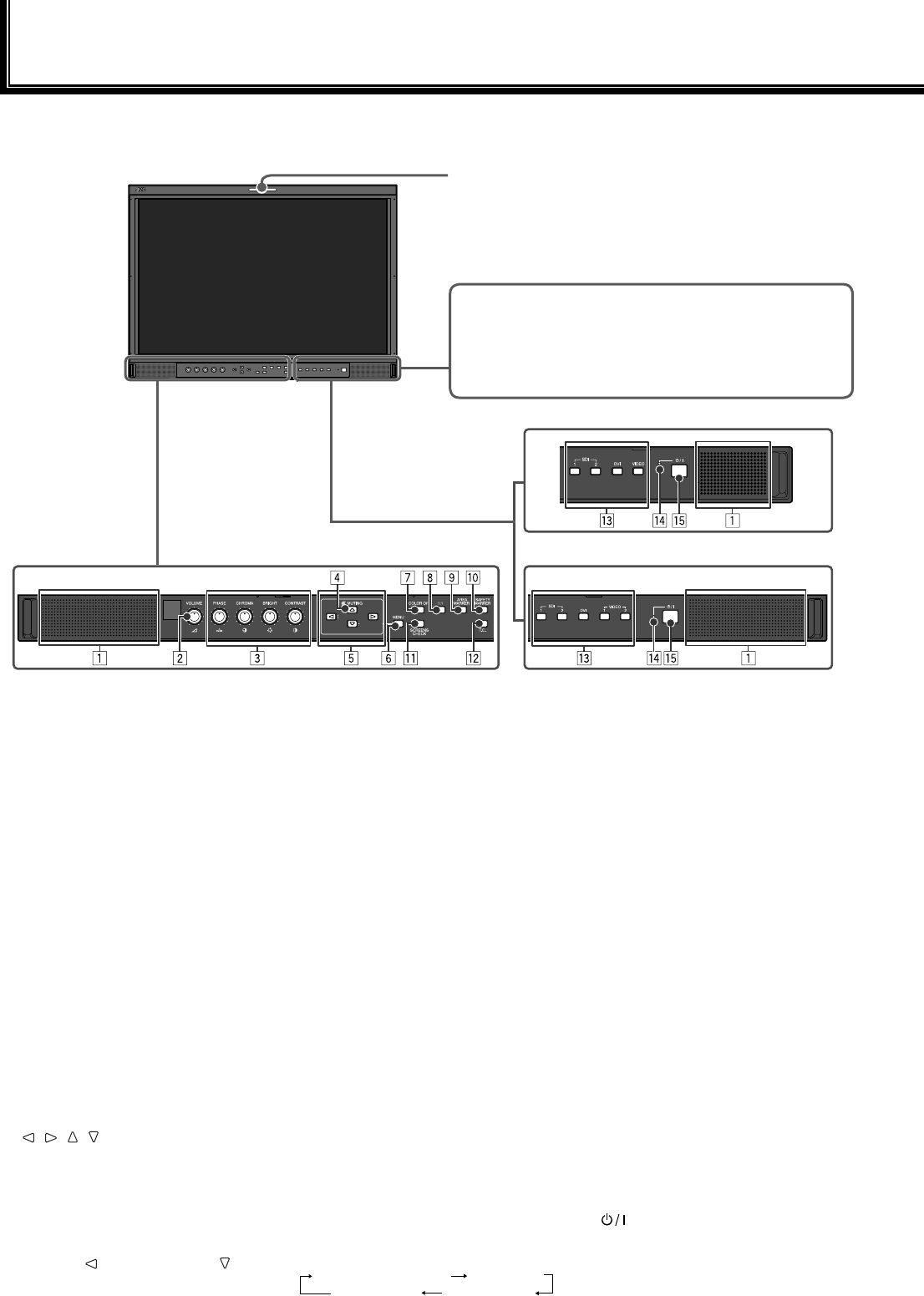
Front panel
1 Speakers (stereo)
The speakers emit the same audio
signal emitted from the AUDIO ASSIGN
(DT-R24L41D) / AUDIO (DT-R17L4D)
(MONITOR OUT) terminals. (☞ “ 6
AUDIO ASSIGN (DT-R24L41D) / AUDIO
(DT-R17L4D) (MONITOR OUT) terminals”
on page 9)
2 VOLUME adjustment knob
Adjusts the volume.
3 Picture adjustment knob
PHASE: Adjusts the picture hue.
CHROMA: Adjusts the picture color density.
BRIGHT: Adjusts the picture brightness.
CONTRAST: Adjusts the picture contrast.
PHASE and CHROMA cannot be
adjusted for certain signal formats.
When “COMPONENT PHASE” is set to
“DISABLE” and an NTSC signal is input,
PHASE can be adjusted (☞ page 15).
4 MUTING button
Turns off the sound when no menu screen
is displayed.
To cancel the function, press the button
again or turn the VOLUME adjustment knob.
Muting function is also canceled when
“BALANCE” of “AUDIO SETTING” in the
MAIN MENU is changed (☞ page 14).
5
/ / / buttons
When a menu screen is displayed
Selects or adjusts menu items. (☞ “The
operation procedure” on page 12)
When no menu screen is displayed
Selects the audio channels of
EMBEDDED AUDIO signals. (☞ “Audio
Channel Selection” on page 11)
Pressing button while holding button
displays the SET-UP MENU. (☞ “The
operation procedure” on page 12)
•
•
•
•
•
6 MENU button
Activates/deactivates the display of
the MAIN MENU. (☞ “The operation
procedure” on page 12)
7 COLOR OFF button/lamp
Displays only the luminance signal.
This function does not work for RGB
input signals.
8 1:1 button/lamp
Displays the picture in the original
resolution of the input signal.
The aspect ratio of the picture may
change depending on the input signal.
9 AREA MARKER button/lamp
Displays/hides the area marker.
Select the style of the area marker
in “MARKER” of the MAIN MENU
(☞ page 13).
This function works only when displaying
the picture in 16:9 aspect ratio.
This function does not work when
“AREA MARKER” or “R-AREA
MARKER” is set to “OFF” in “MARKER.”
p SAFETY MARKER button/lamp
Displays/hides the safety marker.
Adjust the area of the safety marker in
“MARKER” of MAIN MENU (☞ page 13).
This function does not work when
displaying the picture in the 1:1 mode.
This function does not work when
“SAFETY MARKER” or “R-SAFETY
MARKER” is set to “OFF” in “MARKER.”
q SCREENS CHECK button/lamp
Displays only the selected element (R, G,
or B) of the video signal.
Each time you press this button, the
picture changes in the following order.
RGB (Normal screen) Red screen
Blue screen Green screen
•
•
•
•
•
•
•
•
•
w T.C. (time code) button/lamp
Activates/deactivates the display of the time
data (time code) contained in the SDI signal.
(☞ “On the Information Display” on page 11)
Select the time code type in
“INFORMATION” of SET-UP MENU (☞
page 17).
e INPUT SELECT buttons/lamps
Selects an input.
SDI 1: E. AUDIO HD/SD SDI (IN 1)
terminal
SDI 2: E. AUDIO HD/SD SDI (IN 2)
terminal
DVI: DVI-D (HDCP) terminal
DT-R24L41D
VIDEO 1: VIDEO (INPUT 1) terminal
VIDEO 2: VIDEO (INPUT 2) terminal
DT-R17L4D
VIDEO: VIDEO terminal
The lamp for the selected input lights.
r Power lamp
Unlit: The monitor is completely off
(the power switch on the rear
panel is turned off).
Lights in Green:
The monitor is on.
Lights in orange:
The monitor is off (on standby).
Flashes in orange:
The monitor is in the P. SAVE
(power save) mode. (☞ “NO
SYNC ACTION” in “SYNC
FUNCTION” on page 15)
t button
Turns on and off (on standby) the monitor.
The power switch is equipped on the rear
panel of the monitor (☞ 1 on page 8).
•
•
•
Tally lamp
This lamp is controlled by the tally function of the MAKE/TRIGGER
terminal.
You can select the color of the tally lamp from “GREEN” or “RED.”
(☞ “TALLY SELECT” in “FUNCTION SETTING” on page 15 and
“External Control” on page 18)
•
“NO EFFECT” is displayed when you press a button which is
not available for the current input or signal format (the lamp
lights even when the function does not actually work).
The items controlled by the MAKE system cannot be controlled
by the buttons on the front panel (“REMOTE ON” is displayed
and the lamps do not light).
•
•
The illustration of the
monitor is of DT-R24L41D.
Daily Operations
DT-R24L41D
DT-R17L4D