


7
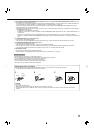
To install the monitor on a wall
You can install the monitor on a wall by changing how the stand
bottom plate is attached.
Installation Only for Authorized Service Personnel
Consult authorized service personnel for the installation of
this unit. Installation instructions must be followed precisely in
order to prevent accidents. We are selling this product with the
understanding that it will be assembled and installed by properly
trained and qualifi ed service personnel.
We are not liable for any damage caused by faulty assembly,
faulty wall mounting, insecure wall mounting, misuse,
alterations, or natural disasters.
Please be aware that screw holes and anchor bolts will remain
in the wall surface if the monitor is removed after having been
mounted to the wall.
Long-term use of the LCD display monitor may result in discoloration
of the wall surface due to heat/air emitted by the display.
Danger
Consult authorized service personnel for the installation and
attachment of this unit to the wall. Do not attempt to mount the unit
by yourself.
This unit weighs 12 kg at maximum (26.5 lbs. at maximum),
including LCD display monitor. Improper assembly or installation
may cause the unit to fall when it is mounted, which may result in
fatal accidents. To prevent this happening, check the strength of
the materials in the mounting surface. Check the material strength
again after mounting as well.
Warning
Using a monitor other than this product may result in damage or
bodily injury due to the LCD display monitor toppling over.
Assemble all screws securely. Failure to do so may result in the
LCD monitor and stand falling down, potentially causing damage or
bodily injury.
This unit does not come with anchor bolts for securing it to walls,
etc. Be sure you have materials on hand as appropriate for the
mounting location.
The monitor should be mounted to a wall that can adequately hold
the total weight of the monitor and stand over a long period of time
and which can adequately withstand earthquakes, conceivable
vibrations, and other external forces.
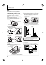
Mounting On Wooden Walls
The weight of the unit should be borne by the wall posts or studs,
and these should be reinforced if insuffi ciently strong. Do not
install the Wall Mounting Unit on walls made of plasterboard or thin
plywood. Use the commercially sold screws best suited for the wall
structure and material.
Mounting On Concrete Walls
Use commercially sold wall anchors capable of supporting the
weight of the LCD monitor.
Do not install the Wall Mounting Unit near the blower or air inlet of
an air conditioner.
Do not install the Wall Mounting Unit in a location subject to
frequent vibration, impact or other external forces.
Do not install the unit in a location where people may hang on it or
lean against it.
Do not block the ventilation holes.
Do not install the monitor on a non-vertical wall.
Caution
Consult authorized service personnel for electrical work. Using
power cords damaged during installation (i.e., exposed or severed
wiring) may result in fi re or electric shock.
Conduct the work with adequate working space. Damage or bodily
injury may result from working under unsuitable conditions.
Avoid mounting this unit in areas where there is electrical wiring or
water pipes, as fi re or electric shock may result.
•
•
•
•
•
•
•
•
•
•
•
•
•
•
•
•
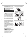
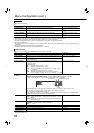
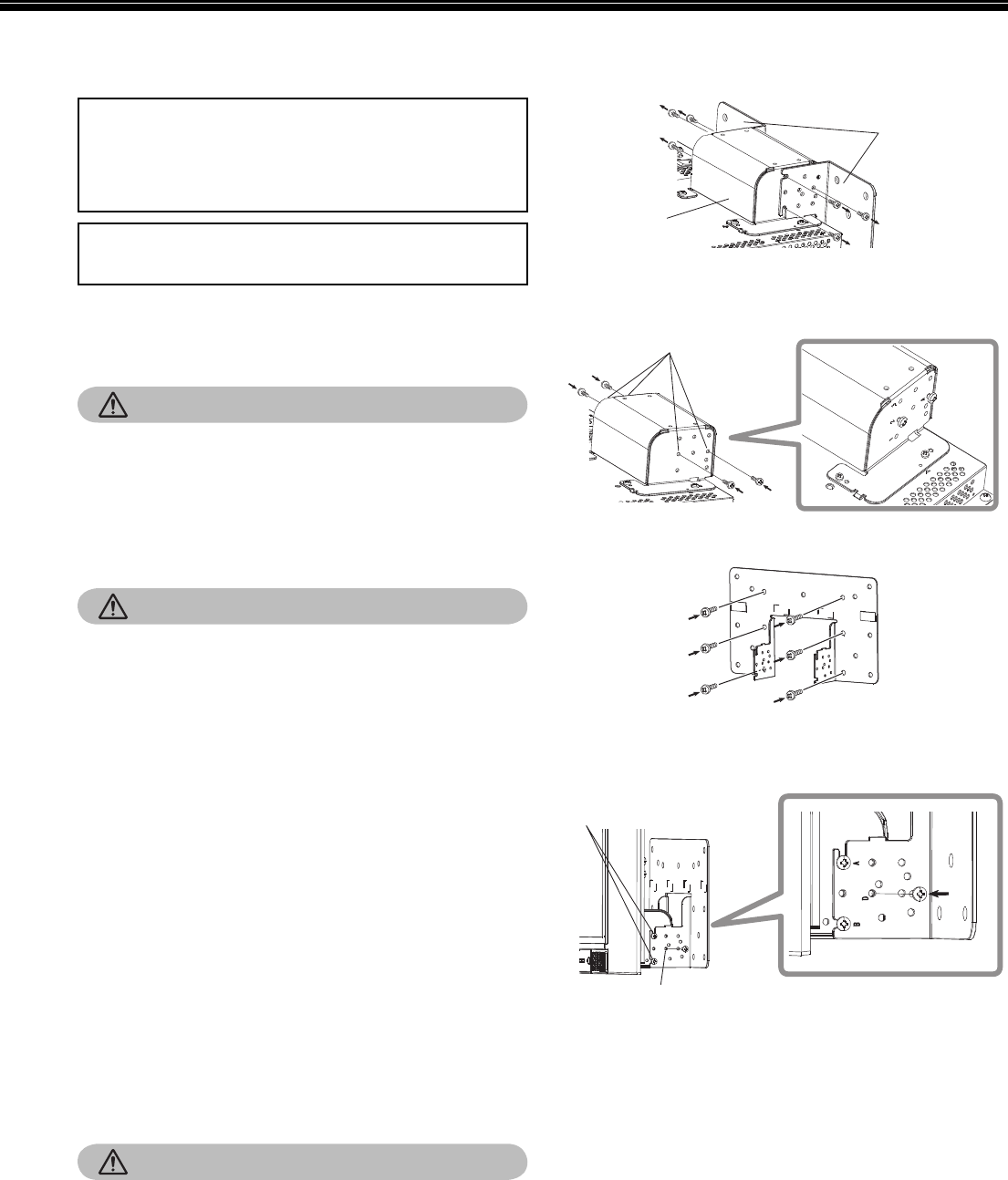
1
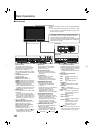
Lay the monitor on a cloth with the LCD panel facing down to
prevent the LCD panel from being damaged. Loosen the stand
screws on the stand support and remove the bottom plate.
Bottom plate
Stand support
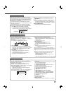
2
Temporarily set the stand screws in screw holes “2” and “4” on the
right and left sides of the stand support.
Tighten the temporarily set stand screws so that they protrude
from the screw holes by about 4 mm.
Stand screws “2” and “4”
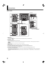
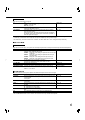
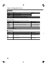
3
Tighten commercially available screws in the 6 holes shown in the
fi gure below to install the monitor on the wall.
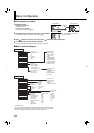
4
Hook the temporarily set screws on the stand support in right and
left recesses “A” and “B” on the bottom plate, tighten the two stand
screws in right and left screw holes “D” and fi nally retighten the
temporarily set screws to lock the stand support and bottom plate.
Recesses “A” and “B”
Screw holes “D”
•