


15
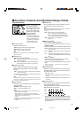
Ⅵ Functions, Contents, and Adjustment Range of items
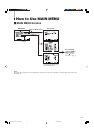
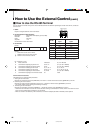
FUNCTION SETTING
Sets the control systems for
the COLOR SYSTEM,
synchronized signal, RUSH
DELAY TIME, colors and
functions of the tally lamp,
groups of the audio output
modes, and MAKE/
TRIGGER terminal.
• Can be also used to adjust
the zooming position of the
picture for the component
signal input, and check the
amount of time that the
monitor has been used.
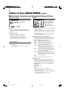
Ⅵ COLOR SYSTEM
Selects the color system.
AUTO:Changes NTSC and PAL automatically.
NTSC:Keeps the color system NTSC.
PAL: Keeps the color system PAL.
NOTE:
Normally select AUTO. However, if the input signal is unstable,
select NTSC or PAL.
Ⅵ SYNC SELECT
Selects the synchronized signal.
INT.: The input video signal is synchronized with the
built-in sync signal.
EXT.: The input video signal is synchronized with an
external signal from an external sync terminal.
Ⅵ RUSH DELAY TIME
Sets the delay time between when the stand-by
button is pressed and when the monitor actually
turns on.
STD.: Power turns on about 1 second after the stand-by
button is pressed.
SLOW: Power turns on about 3.2 seconds after the stand-
by button is pressed.
NOTE:
It is recommended to apply “SLOW” to some of the monitors if you
need to turn on multiple monitors at the same time. You can control
the rush current of the entire system.
Ⅵ TALLY SELECT
Selects the color of the tally lamp on the upper right
of the front panel.
GREEN:The tally lamp lights in green.
RED: The tally lamp lights in red.
NOTES:
• “TALLY SELECT” does not appear on the menu when both the
following conditions are applied:
– When selecting “TA. SEL” to a pin terminal of the MAKE/
TRIGGER terminal in “REMOTE SYSTEM” of SET-UP MENU.
– When activating the external control.
☞ page 19
• The tally lamp is controled using the MAKE/TRIGGER terminal of
the REMOTE (external control) terminals.
☞ page 19
Ⅵ FORMAT IND.
Sets the tally lamp as the format indicator to show
the format of the signal currently input.
NOTE:
When setting FORMAT IND. to ON, you cannot use the tally lamp
function of the MAKE/TRIGGER terminals.
☞ page 19
ON: Uses the lamp as the format indicator.
Green: Shows the HD SDI signal is input.
Red: Shows the SD SDI signal is input.
Orange: Shows the composite signal is input.
OFF: Uses the lamp as the tally lamp.
☞ page 19
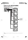
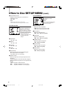
Ⅵ REMOTE SYSTEM
Sets the MAKE/TRIGGER terminal.
☞ “How to Use the MAKE/TRIGGER Terminal” on page 19
CONTROL FORM:
Selects the control system for the MAKE/TRIGGER terminal.
MAKE: Selects the make contact system as the external
control method.
TRIG.: Selects the trigger system as the external control
method.
SET: You can apply the functions to the 1st to 6th pin
terminals of the MAKE/TRIGGER terminal as you
want.
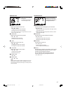
PORT F1 – PORT F6:
Selects the function to be applied to the 1st to 6th pin
terminals of the MAKE/TRIGGER terminal.
☞ “How to Use the MAKE/TRIGGER Terminal” on page 19
NOTE:
You can set “PORT F1” – “PORT F6” only when “CONTROL
FORM” is set to “SET.”
Ⅵ ZOOM WINDOW
Adjusts the horizontal position of the zooming area.
This item appears on the menu only when using the
Component Unit (option).
• –30 O 00 O +30
–: Moves the horizontal position of the zooming area to
the left.
+: Moves the horizontal position of the zooming area to
the right.
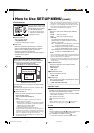
Ⅵ E. AUDIO GROUP
Sets the group of the available audio output modes
selected by the MENU control.
This item appears on the menu only when using the
Multi-Format SDI Unit (option).
1G:
1ch 2ch 3ch 4ch 1-2ch 3-4ch 1-4ch
2G:
5ch 6ch 7ch 8ch 5-6ch 7-8ch 5-8ch
1-2G:
AUTO 5-8ch 1-4ch 7-8ch 5-6ch 3-4ch
1ch 2ch 3ch 4ch 5ch 6ch 7ch 8ch 1-2ch
• When HD/SD SDI signal including EMBEDDED AUDIO
signal is input, you can select the channel of the audio
signal output from the audio output terminal by changing
the audio output mode. Refer also to the Multi-Format
SDI unit’s manual.
EN14-24_LCT1811-001A-H.p65 05.5.16, 8:54 PM15