


18
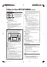
How to Use SET-UP MENU (cont.)
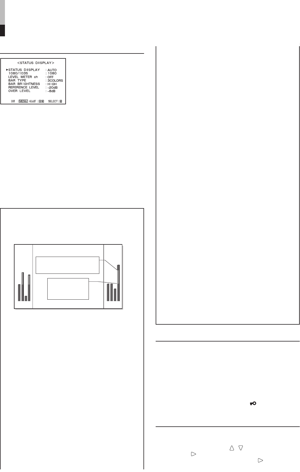
STATUS DISPLAY
Sets the items related to the
display screens, such as the
status display or the AUDIO
LEVEL METER display.
• Can also be used to set the
1080/60i or 1035/60i signal
displayed correctly.
Ⅵ STATUS DISPLAY
Sets the status display.
• AUTO/MANUAL/OFF
☞ “About the status display” on page 5
Ⅵ 1080/1035
When the component signal is input, the monitor
does not automatically discriminate the 1080/60i
signal from the 1035/60i signal. Set this item
according to the input signal format.
This item appears on the menu only when using the
Component Unit (option).
• 1080/1035
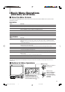
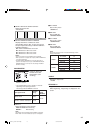
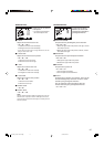
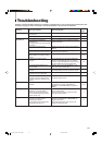
Setting the AUDIO LEVEL METER display
You can check the conditions of the current EMBEDDED
AUDIO signals on the AUDIO LEVEL METER display.
1 2 3 4
5 6 7 8
AUDIO LEVEL METER display example
LEVEL METER ch: 1-8, BAR TYPE: 3COLORS
OVER LEVEL
[–10dB/–8dB/–6dB/–4dB/–2dB]
REFERENCE
LEVEL [–20dB/
–18dB]
Audio channels and OVER/
REFERENCE LEVEL indication
CONTROL LOCK
Ⅵ CONTROL LOCK
Prohibits the monitor operations except turning on/off
the monitor and deactivating this function.
• Operating the monitor by the external control is available
if this function is activated.
ON: Activates this function.
OFF: Deactivates this function.
NOTE:
• When “CONTROL LOCK” is set to “ON,” “ Control lock on!”
appears on the screen if you try to operate the monitor.
all reset
Resets all SET-UP MENU items to factory-preset
values.
1.Move the MENU control to / to select “all reset,” then
move it to
. Confirmation message is displayed.
2.To initialize, move the MENU control to
.
To cancel the initialization, press the MENU control.
The following items are the settings for the AUDIO LEVEL
METER display.
The following items appear on the menu only when using
the Multi-Format SDI Unit (option).
Ⅵ LEVEL METER ch
Selects the audio channels used in the AUDIO
LEVEL METER display.
• OFF/1:2/12:34/31:24/123:456/1-8
NOTES:
• This item does not appear on the menu when both the
following conditions are applied:
– When selecting “L. METER” to a pin terminal of the MAKE/
TRIGGER terminal and “MAKE” to “CONTROL FORM” of
“REMOTE SYSTEM” in SET-UP MENU.
– When activating the external control.
☞ “REMOTE SYSTEM” on page15 and page 19
• Numbers indicate the audio channel. The channel input level
indicated on the left side of “:” is displayed on the left side of
the screen, and the channel input level indicated on the right
side of “:” is displayed on the right side of the screen.
• The AUDIO LEVEL METER display does not appear when
this item is set to OFF.
• When “1-8” is selected, the channel input level for 1, 2, 3 and 4 is
displayed on the left side of the screen, and the channel input
level for 5, 6, 7 and 8 is displayed on the right side of the screen.
• The AUDIO LEVEL METER display moves to inside of the
screen when the ZOOM function is operated.
Ⅵ BAR TYPE
Selects the color of the AUDIO LEVEL METER
display.
W. 100: White color display
W. 50: White (half transparent) display
3COLORS:
The AUDIO LEVEL METER display uses three
different colors (red, yellow and green) to indicate
variations in input levels.
Red: Displayed when the audio input is at the same
level set in “OVER LEVEL” or higher.
Yellow: Displayed when the audio input is at the same
level set in “REFERENCE LEVEL” or higher.
Green: Displayed when the audio input is lower than
the level set in “REFERENCE LEVEL.”
NOTES:
• For W. 100 and W. 50, the line indication for the standard input
level set in the “REFERENCE LEVEL” is displayed. Input level
set in the “OVER LEVEL” is not displayed.
• As for the audio channel bar display with no signal input, white
is displayed for the 3COLORS setting, and gray is displayed
for other settings.
Ⅵ BAR BRIGHTNESS
Selects the brightness of the AUDIO LEVEL
METER display.
HIGH: Brighter
LOW: Darker
Ⅵ REFERENCE LEVEL
Sets the standard input level.
• –20dB/–18dB
Ⅵ OVER LEVEL
Sets the input level’s lower limit indicated in red for
the “3COLORS” display.
• –10dB/–8dB/–6dB/–4dB/–2dB
EN14-24_LCT1811-001A-H.p65 05.5.16, 9:05 PM18