


19
How to Use the External Control
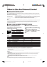
Ⅵ About the External Control
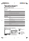
The Multi-Format Monitor has two external control terminals.
One is the MAKE/TRIGGER terminal, which allows the monitor to be controlled by the MAKE (make contact) or TRIG. (trigger)
method selected in the function setting.
MAKE (make contact system): Controls the function by short-circuiting the corresponding pin terminal to the GND pin terminal, or
disconnecting (opening) it.
TRIG. (trigger system): Controls the function by inputting the pulse signal instantaneously to the corresponding pin terminal.
* MAKE or TRIG. are selected from “REMOTE SYSTEM” in SET-UP MENU.
The other terminal used for remote control is the RS-485 terminal, and this allows the monitor to be controlled by serial
communication.
NOTE:
Control priority is in the following order; 1 MAKE/TRIGGER terminal > 2 RS-485 terminal > 3 Front panel buttons or menu functions of the monitor.
• When using the make contact system, you cannot use the functions which are applied to the MAKE/TRIGGER terminal operating the front panel
buttons or the menu of the monitor. (When using the trigger system you can also use those functions operating the monitor directly.)
• When controlling the monitor using RS-485 terminal, you cannot use the functions operating the front panel buttons or the menu of the monitor
except turning on or off the monitor.
*1 : The TRIG. (trigger) system switches each function by short-circuiting for approx. 1 second.
*2 : When selecting the TRIG. (trigger) system, these functions cannot be controlled if no signal is input.
*3 : Activates the settings of the items with “R-” or without “R-” in the “MARKER” menu. ☞ “MARKER” on page 12
*4 : This function do not work if you set “FORMAT IND.” in “FUNCTION SETTING” of SET-UP MENU to “ON.”
*5 : Tally lamp Control and External control (the 7th pin terminal) can be controlled by the MAKE (make contact) system even when you select the
“TRIG.” (trigger) system.
*6 : This function works only when using the Multi-Format SDI Unit (option).
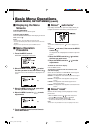
Operation
1. Short-circuit the 7th pin terminal (External control) to the 8th pin terminal (GND) so that the monitor can be controlled by the
external control.
2. When selecting the “MAKE” (make contact) system, operate each function by short-circuiting the corresponding pin
terminal to the 8th pin terminal (GND) or opening it.
When selecting the “TRIG.” (trigger) system, operate each function by Pulse control, that is short-circuiting the
corresponding pin terminal to the 8th pin terminal (GND) for about 1 second.
NOTES:
• When controlling INP. A/B/C/D, only one terminal must be short-circuited. (Other terminals must be opened.)
• When selecting the “TRIG.” (trigger) system, you can operate only one function at a time. Operate the functions one by one.
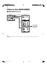
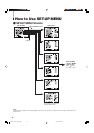
Ⅵ How to Use the MAKE/TRIGGER Terminal
1234 5678
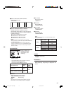
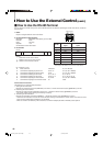
Ⅵ Function of the MAKE/TRIGGER terminal
The followings are the configurations and the functions of the
pin terminals of RJ-45 connector. You can change the
functions applied to the 1st to 6th pin terminals by setting
“REMOTE SYSTEM” of SET-UP MENU.
Caution:
This is a female
connecter.
NO.
1
2
3
4
5
6
7
8
INP. A
INP. C
MARKER
ASPECT
TALLY
L. METER
Functions to be controlled
Changes the input to INPUT A
Changes the input to INPUT C
Turns on/off MARKER
Changes ASPECT
Controls the tally lamp
Turns on/off AUDIO LEVEL
METER
External control
GND
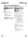
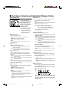
Ⅵ To change the functions applied to the pin
terminals
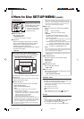
1. Display SET-UP MENU, then move the MENU control to
/ to select “REMOTE SYSTEM,” then move it to .
2. Move the MENU control to
/ to select “CONTROL
FORM,” then move it to / to select “SET.”
3. Move the MENU control to / to select the number of
the pin terminal (PORT F1 – PORT F6) you want to set,
then move it to / to select the function.
NOTE:
You cannot apply two or more functions to one terminal.
Display
INP. A
INP. B
INP. C
INP. D
CO. OFF
MARKER
ASPECT
MA. SEL
TALLY
TA. SEL
STATUS
L. METER
Functions to be controlled
Changes the input to INPUT A
Changes the input to INPUT B
Changes the input to INPUT C
Changes the input to INPUT D
Turns on/off COLOR OFF
Turns on/off MARKER
Changes ASPECT
Selects the MARKER settings
Controls the tally lamp
Selects the color of the tally lamp
Turns on/off the status display
Turns on/off AUDIO LEVEL METER
Opening
Invalid
Invalid
Invalid
Invalid
Off
Off
4:3
Selects the settings without “R-”
Off
Green
Off
Off
Short-circuiting
Valid
Valid
Valid
Valid
On (Monochrome screen)
On
16:9
Selects the settings with “R-”
On
Red
On
On
*1
*2
*2
*3
*4, 5
*6
Functions controlled by the MAKE/TRIGGER Terminal
EN14-24_LCT1811-001A-H.p65 05.5.13, 1:54 PM19