


10
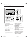
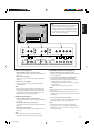
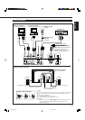
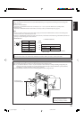
Precautions
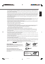
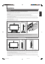
• Before making connections, turn off all the equipment.
• Plugs should be firmly inserted; poor connection could cause noise.
• To unplug a cord, be sure to grasp its plug and pull it out.
• Connect the power cord after having finished all other connections.
• Refer also to the user manual of each piece of equipment.
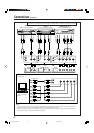
Available Signals
Video signals
The following signals can be input to this Monitor:
• VIDEO A and VIDEO B terminals accept — PAL, PAL60, NTSC, NTSC4. 43, and SECAM signals.
• COMPONENT/RGB B terminals accept — 480i, 576i, 480p, 576p, 720/60p, 1080/50i, and 1080/60i (1035/60i) signals. (You
need to set “RGB/COMPO.” to “COMPO.” on the menu (see page 21).
(For GM-V42PCE, GM-V42PCEG and GM-V42PCEB, to input the above signals, you need to install the video input unit
(IF-C42P1G), which is separately purchased.)
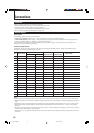
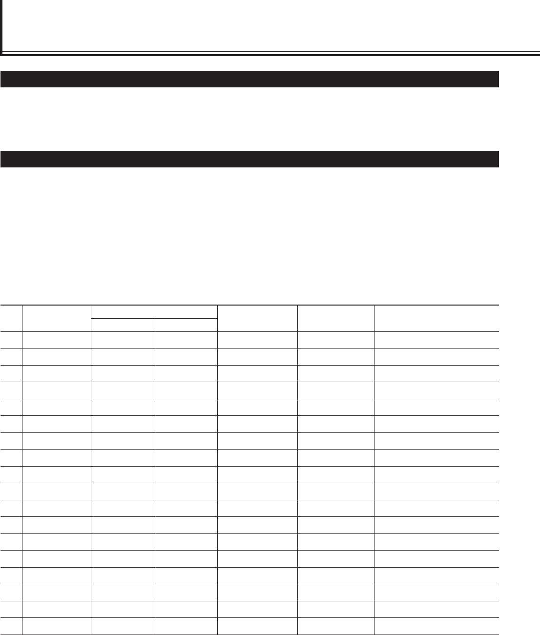
Computer signals (Preset)
This Monitor has 18 preset video modes for the most popular industrial standard, and the signals of the following image
resolutions can be input to the RGB input terminals.
1 PC98 640 400 24.8 56.4 Non-interlace
2 VGA400-70 640 400 31.5 70.1 Non-interlace
3 VGA480-60 640 480 31.5 59.9 Non-interlace
4 VGA480-72 640 480 31.7 72.8 Non-interlace
5 VGA480-75 640 480 37.5 75.0 Non-interlace
6 WVGA-60 852 480 31.7 60.3 Non-interlace
7 MAC13” 640 480 35.0 66.7 Non-interlace
8 SVGA-56 800 600 35.2 56.3 Non-interlace
9 SVGA-60 800 600 37.9 60.3 Non-interlace
10 SVGA-72 800 600 48.1 72.2 Non-interlace
11 SVGA-75 800 600 46.9 75.0 Non-interlace
12 XGA-60 1024 768 48.4 60.0 Non-interlace
13 XGA-70 1024 768 56.5 70.1 Non-interlace
14 XGA-75 1024 768 60.0 75.0 Non-interlace
15 XGA-85 1024 768 68.7 85.0 Non-interlace
16 XGA+-75 1152 864 67.5 75.0 Non-interlace
17 RGB15K-60 — — 15.7 59.9 Interlace
18 RGB15K-50 — — 15.6 50.0 Interlace
Notes:
• When a signal other than listed above is input, a part of the screen may become void or an unnecessary picture may appear.
• Signals, though they are within the acceptable range of frequencies, may not be displayed normally, depending on the signal
type.
• Depending on the connected equipment, the Monitor may not be compatible with composite sync (Cs) or G on sync signals.
• When a preset mode signal is input, the vertical frequency displayed on the screen will have an “*” shown at its right top
position.
• When the No. 6 signal is input, change the aspect ratio to “FULL” with the ASPECT button (page 15) on the remote control or
from the “FUNCTION SELECT” menu (page 21).
• When No. 8 to No. 16 signals are input, thin lines may become obscure for their signal frequencies are higher than the screen
resolution.
Connections
Screen resolution
Horizontal
Vertical
Horizontal
Frequency (kHz)
Vertical
Frequency (Hz)
Signal name Scan systemNo.
04_13_GM_V42[E].p65 03.6.23, 4:42 PM10