


6
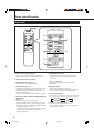
Parts Identification (Continued)
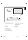
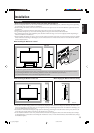
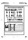
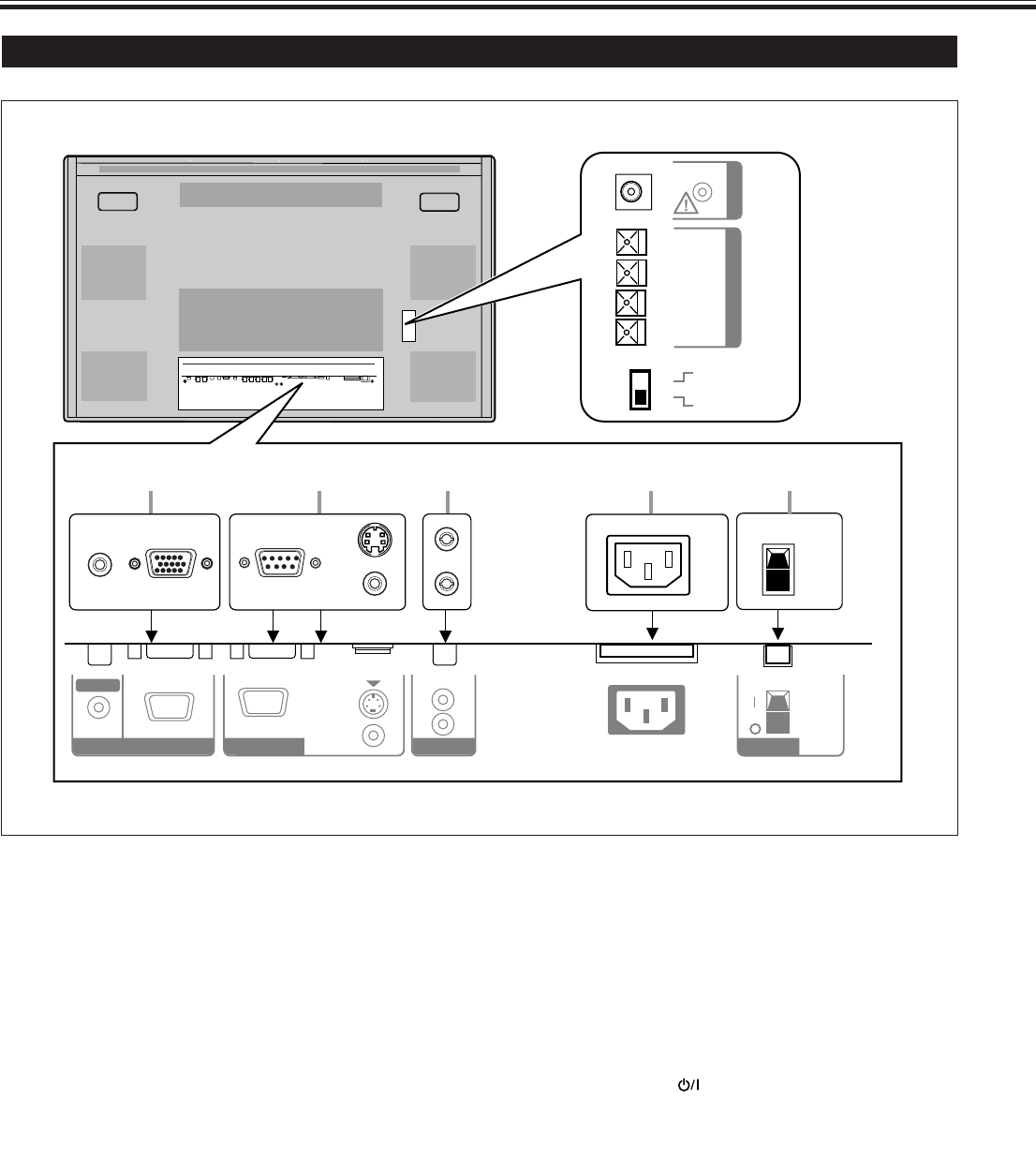
Monitor: Rear Views
1 RGB A input terminals (page 11)
• D-sub, 15 pin
Connect to the video output terminal of a personal
computer.
• AUDIO IN (stereo mini jack)
Connect to the audio output terminal of a personal
computer.
2 REMOTE terminals (pages 11 and 13)
• RS-232C (D-sub, 9 pin)
Connect to the RS-232C terminal of a personal computer.
For the control method using this terminal, consult an
authorized JVC dealer.
• MAKE terminal (mini DIN 4pin)
Connect an external control unit. (See page 13.)
• WIRED terminal (stereo mini jack)
Connect a wired remote control unit to this terminal.
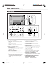
Note:
• When the above three terminals are used at the same
time, transmitted commands through the MAKE
terminal have priority over those through the other
terminals.
3 AUDIO OUT terminals (pin jack) (page 11)
Connect to the audio input terminals of external
equipment such as an amplifier.
4 AC IN terminal (page 11)
Connect the supplied power cord to this terminal.
5 POWER switch (page 14)
Setting this switch to “| (on)” will put the Monitor into
standby mode, allowing you to turn on and off the power
using the POWER or
button either on the remote
control or on the Monitor.
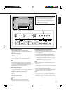
6 OPTION terminal (page 13)
Connect the power cord of the Cooling Fan Unit (not
supplied) when installing the Monitor vertically.
7 SPEAKER OUT L/R terminals (page 11)
Connect external speakers, such as unique JVC speakers
(not supplied), etc.
8 INTERNAL/EXTERNAL (built-in speaker/external
speaker) selecting switch (page 11)
INTERNAL: To use built-in speakers.
EXTERNAL: To use external speakers.
AC INAUDIO
L
OUT
R
RGB A
AUDIO
IN
REMOTE
RS-232C
WIRED
MAKE
EXTERNAL
(
9
9
(
R
SPEAKER OUT
L
INTERNAL
POWER
OPTION
1 2 3 4 5
7
8
6
04_13_GM_V42[E].p65 03.6.23, 4:42 PM6