


11
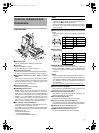
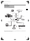
Connecting Cables
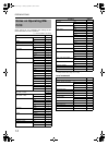
Connect the cables for this device to the camera.
Connect the cable for this device to the camera terminal.
MEMO
• Turn off the device before connecting cables.
• Do not touch the plug terminals when connecting.
• Insert the DC cable plug all the way in until it locks.
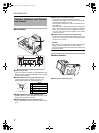
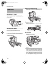
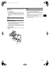
Connecting the Viewfinder (VF-P400)
1. Loosen the lock lever.
Turn the viewfinder lock lever counterclockwise and
loosen the lock lever.
2. Attach the viewfinder.
Slide the viewfinder forward along the viewfinder holder
guides on the top of this device.
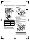
3. Tighten with the lock lever.
Turn the viewfinder lock lever clockwise and tighten the
lock lever.
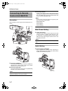
4. Connect the cables.
Connect the viewfinder cable and conversion plug and
connect the conversion plug to the viewfinder output ter-
minal (20 pin) of this device.
MEMO
• Signals are not output from the VF OUTPUT (Y/P
B/PR/
RGB) BNC terminal on the side of this device.
• Do not connect anything other than the specified view-
finder to the viewfinder output terminal (20 pins).
Cable (type) Camera terminal
GENLOCK (BNC) 1 GENLOCK IN
REMOTE (Round 6-pin) 2 REMOTE
DC OUTPUT (XLR 4-pin) 3 DC INPUT
VIDEO (RCA) 4 VIDEO OUTPUT
Y (BNC) 5 Y IN
P
B (BNC) 6 P
B
IN
P
R (BNC) 7 P
R
IN
STUDIO (Round 10-pin) 8 STUDIO
VF (Round 20-pin) 9 VF
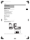
DC INPUT
REMOTE
HD/SD
GENLOCK/AUX IN
P
TC OUT
IEEE 1394
CH2-AUDIO OUT-
CH1 VIDEO
STUDIO
P
TC IN
Y
SDI
9
4
5
6
7
8
1
2
3
2.
1.
3.
4.
e_ka250.book Page 11 Tuesday, September 5, 2006 4:10 PM