


PREPARATIONS
12
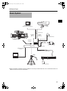
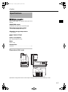
Connecting to Remote
Control Unit RM-P210
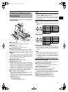
Connection
Switch off RM-P210 power supply before attempting the con-
nection.
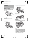
1. Connecting the RM-G210
Connect this unit’s RM multi-pin connector and RM-P210
using the 26 pin camera cable. Length of the camera
cable should not be longer than 100 m.
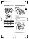
2. Connecting the DT-109U
Connect the Headset DT-109U plug to the [INTERCOM]
terminal to use an intercom headset.
MEMO
This device supports only DYNAMIC-type headset. CAR-
BON-type headphones cannot be connected.
3. Connecting a Monitor
Prompter video (RM-P210 [AUX VIDEO INPUT] terminal
input signal) from RM-P210 can be verified by connecting
this unit’s [PROMPTER OUTPUT] terminal located in the
front to a monitor using a BNC cable.
MEMO
• Power for this unit and the camera are supplied by RM-
P210 via the 26 pin camera cable.
• 26 pin camera cable
VC-P110 (5 m)
VC-P112 (20 m)
VC-P113 (50 m)
VC-P114 (100 m)
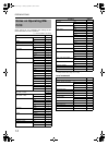
Menu Screen Setting
1. Output Signal Setting
Composite video signal is always output from the RM
multi-pin connector. In addition, RGB component, Y/P
B
/
P
R
component or YC separate signal can also be output.
Select the output signal using the OUTPUT item on the
SYSTEM menu screen
MEMO
Sync signals are superimposed onto RGB component sig-
nals.
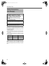
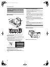
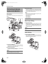
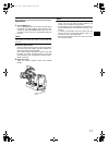
Switch Setting
1. Enabling/disabling INCOM MIC
Set the [INCOM MIC ON/OFF] switch depending on
whether headset microphone will be used. Set the switch
to [ON] use the headset microphone.
4.
INCOM MIC
ON/OFF switch
e_ka250.book Page 12 Tuesday, September 5, 2006 4:10 PM