


5
Thank you for purchasing this product.
(These instructions are for: KA-HD250U.)
Before operating this unit, read the instruction manual care-
fully in order to make sure that the best possible perfor-
mance is obtained.
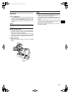
Main Features
Equipped with Analog 26P Camera
Connector
Connect the Remote Control Unit RM-P210 (sold separately)
to control this unit from up to a distance of 100 m away. In
this case, the remote control unit provides power for the
camera and thus there is no requirement for a separate
power supply for the camera.
Multi-system Output
Output composite signals and RGB component, Y/PB/PR
component, or YC separate signals from the 26P camera
connector. (Selectable with the menu switch.)
Equipped with Intercom Terminal
Use a headset to communicate with the remote control unit
operator. (Dynamic only)
Equipped with Prompter Output Ter-
minal
Output prompter video from the remote control unit as com-
posite signals.
VF-P400 4-inch Viewfinder Compati-
ble
A general-purpose viewfinder can also be connected.
Features External Monitor Compo-
nent Terminals (BNC × 3)
Contents
INTRODUCTION
Main Features . . . . . . . . . . . . . . . . . . . . . . . . . . . . . . . . . . .5
Operating Precautions . . . . . . . . . . . . . . . . . . . . . . . . . . . . .6
Regarding Genlock Signal and Adjustment of System
Phase . . . . . . . . . . . . . . . . . . . . . . . . . . . . . . . . . . . .6
Controls, Indicators and Connectors . . . . . . . . . . . . . . . . . .7
Front Section. . . . . . . . . . . . . . . . . . . . . . . . . . . . . . . . . .7
Rear Section. . . . . . . . . . . . . . . . . . . . . . . . . . . . . . . . . .8
Bottom Section . . . . . . . . . . . . . . . . . . . . . . . . . . . . . . . .8
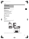
PREPARATIONS
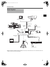
Basic System . . . . . . . . . . . . . . . . . . . . . . . . . . . . . . . . . . . .9
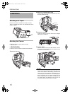
Installation . . . . . . . . . . . . . . . . . . . . . . . . . . . . . . . . . . . . .10
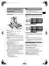
Mounting on a Tripod . . . . . . . . . . . . . . . . . . . . . . . . . .10
Mounting the Camera . . . . . . . . . . . . . . . . . . . . . . . . . .10
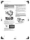
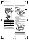
Connecting Cables . . . . . . . . . . . . . . . . . . . . . . . . . . . .11
Connecting the Viewfinder (VF-P400) . . . . . . . . . . . . .11
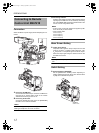
Connecting to Remote Control Unit RM-P210 . . . . . . . . . .12
Connection . . . . . . . . . . . . . . . . . . . . . . . . . . . . . . . . . .12
Menu Screen Setting . . . . . . . . . . . . . . . . . . . . . . . . . .12
Switch Setting . . . . . . . . . . . . . . . . . . . . . . . . . . . . . . . .12
Operation . . . . . . . . . . . . . . . . . . . . . . . . . . . . . . . . . . .13
Notes on Operating RM-P210 . . . . . . . . . . . . . . . . . . . . . .14
OTHERS
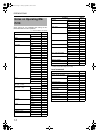
Specifications . . . . . . . . . . . . . . . . . . . . . . . . . . . . . . . . . . .15
Dimensions . . . . . . . . . . . . . . . . . . . . . . . . . . . . . . . . . .15
e_ka250.book Page 5 Tuesday, September 5, 2006 4:10 PM