


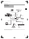

8
INTRODUCTION
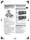
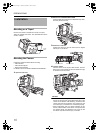
Controls, Indicators and Connec-
tors (Cont’d)
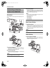
Rear Section
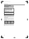
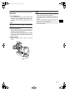
g[TALLY] TALLY Lamp
Lights up red when GY-HD250 is in RECORDING mode.
Blinks red when preparing RECORDING mode and lights
up green when in stand-by.
h[INTERCOM] Intercom Input Terminal (XLR 5 Pin)
Input terminal for intercom headset. (Dynamic only)
Recommended headset: DT109 (Beyerdynamic)
i[INTERCOM MIC] Intercom Mic [ON/OFF] Switch
[ON/OFF] switch for intercom headset microphone. Set to
[ON] to use the headset microphone.
j[INTERCOM LEVEL] Intercom Receiver Volume
Use for adjusting the intercom headset receiver volume
level.
k[CALL] CALL button/Power indicator
Lights green when the studio adapter is turned on.
Press to send call signal to the remote control unit opera-
tor if intercom headset is not in-use.
Button indicator changes from green to red when the but-
ton is pressed.
When this button is pressed and held down, call signal is
sent to the remote control unit and the [TALLY] indicator
blinks. Once the [CALL] button is released, call signal is
no longer sent and the [TALLY] indicator of the remote
control unit turns off.
l[DC INPUT] DC Power Input Terminal (XLR 4 Pin)
Connect DC power to this terminal if Remote Control Unit
RM-P210 is not connected. For DC power supply, use the
IDX IA-60a or VL-2PLUS.
CAUTION
When cable is connected to the DC INPUT terminal while
supplying power from the RM-P210, power will flicker.
Turn off connected devices when connecting a cable to the
DC INPUT terminal.
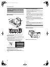
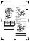
Bottom Section
mScrew Holes for Mounting Tripod
Signal
1 MIC (H)
2 MIC (C)
3 EAR (C)
4 EAR (H) – LEFT
5 EAR (H) – RIGHT
INTERCOM
INTERCOM MIC
INTERCOM LEVEL
CALL
DC INPUT
ON
OFF
MIN
MAX
PUSH
hi jkl
g
1
3
2
5
4
(Surface profile)
m
e_ka250.book Page 8 Tuesday, September 5, 2006 4:10 PM