


7
Controls, Indicators and
Connectors
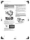
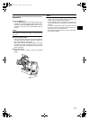
Front Section
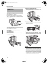
1Viewfinder Holder
Use for mounting the VF-P400 4-inch Viewfinder.
2Lock Lever
Fastens the camera to this unit.
X See “Mounting the Camera” on page 10.
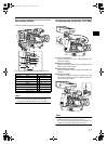
3[VF OUTPUT] round 20-pin
Connect the VF-P400 4-inch Viewfinder (sold separately).
X
See “Connecting the Viewfinder (VF-P400)” on page 11.
4[PROMPTER OUTPUT] Prompter Output Terminal
(BNC)
The prompter video signal input to the [AUX] input termi-
nal of the remote control unit is output from this terminal
via the RM multi-pin connector. Composite signal is out-
put. Video monitor is connected here.
5[VF] Viewfinder Cable
Connect to the VF terminal of GY-HD250.
6[BREAKER] Breaker Switch
Breaker switch trips and cuts off power if the power con-
sumed is higher than the rated capacity. If the breaker
switch trips, confirm that there are no abnormalities and
that the power consumption does not exceed the rated
wattage. If no abnormalities are detected, press the
breaker switch before turning the power on again to put
this unit in the operating status. If this unit still does not
function properly, consult your JVC-authorized dealer.
7[VF OUTPUT] (Y/P
B/PR/RGB) BNC×3
Component output terminal for viewfinder.Use when con-
necting a Viewfinder other than VF-P400.
The HD/SD (from the GY-HD250) and composite video
signal (from the RM-P210) can be switched. Use the GY-
HD250 menu to set.
Recommended viewfinder:
• DM-3106 (Astrodesign)
• V-R70P-HAD (Marshall Electronics)
MEMO
• When the viewfinder is connected to this terminal, the
signal is not output correctly even if the viewfinder is con-
nected to the 3 [VF OUTPUT] terminal.
• When connected to the Y/P
B
/P
R
terminal of the monitor,
the return video signal from the RM-P210 appears in
black and white.
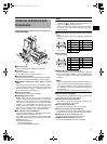
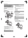
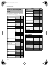
8[TALLY OUTPUT] Tally Signal Output Terminal (D-sub
9 pin)
Output tally signals. Use when connecting a VF other than
VF-P400.
9[TALLY INPUT]
Input tally signals.
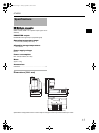
0[RM] RM Multi-pin Connector (26 Pin)
Connect to Remote Control Unit RM-P210 by using the
26-pin camera cable. In addition, power is supplied to this
unit and the camera from the remote control unit via this
connector.
MEMO
• Output Composite video signal and RGB component, Y/
P
B/PR component and YC separate signals from the out-
put terminal of RM-P210. Select the output signal using
the “OUTPUT” item on the “SYSTEM” menu screen on
the GY-HD250.
• SD1 and HD signal cannot be output to the RM-P210.
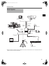
aGenlock Output Cable (BNC)
Output cable for synchronization signals. Connect to the
GENLOCK output terminal of GY-HD250.
bComposite Video Input Cable (RCA)
Input cable for composite video signals. Connect to the
VIDEO output terminal of GY-HD250.
cDC Output Cable (XLR 4pin)
Connect to the DC INPUT terminal of GY-HD250.
dComponent Y/P
B/PR Input Cable (BNC×3)
Input cable for component video Y/P
B/PR signals. Connect
to the each of the Y/P
B/PR output terminals of GY-HD250.
e[CONTROL] Control Cable (Round 9 pin)
Connect to the STUDIO terminal of GY-HD250.
f[REMOTE] Remote Cable (Round 6 pin)
Connect to the REMOTE terminal of GY-HD250.
1
2
3
4
5
7
8
9
0
a
b
c
d
e
f
6
Signal Signal
1 NC 6 NC
2 RM_PREVIEW 7 RM_TALLY
3 NC 8 NC
4 NC 9 NC
5 GND
Signal Signal
1 NC 6 NC
2 TALLY_IN 7 NC
3 NC 8 NC
4 NC 9 NC
5 GND
51
96
(Surface profile)
51
96
(Surface profile)
e_ka250.book Page 7 Tuesday, September 5, 2006 4:10 PM