


14
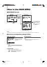
How to Use SET-UP MENU (cont.)
7 Functions and Adjustment Range of Items
FUNCTION SETTING
Sets the control systems for
the COLOR SYSTEM,
synchronized signal, RUSH
DELAY TIME, colors of the
tally lamp, groups of the
audio output modes, and
MAKE/TRIGGER terminal.
• Can be also used to check the amount of time that
the monitor has been used.
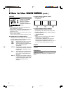
7 COLOR SYSTEM
Selects the color system.
AUTO: Changes NTSC and PAL automatically.
NTSC: Keeps the color system NTSC.
PAL: Keeps the color system PAL.
NOTE:
• Normally select “AUTO.” However, if the input signal is
unstable, select “NTSC” or “PAL.”
7 SYNC SELECT
Selects the synchronized signal.
INT.: The input video signal is synchronized
with the built-in sync signal.
EXT.: The input video signal is synchronized
with an external signal from an external
sync terminal.
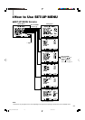
7 RUSH DELAY TIME
Sets the delay time between when the stand-by
button is pressed and when the monitor actually
turns on.
STD.: Power turns on about 1 second after the
stand-by button is pressed.
SLOW: Power turns on about 3.2 seconds after
the stand-by button is pressed.
NOTE:
• It is recommended to apply “SLOW” to some of the
monitors if you need to turn on multiple monitors at the
same time. You can control the rush current of the entire
system.
7 TALLY SELECT
Selects the color of the tally lamp on the upper right
of the front panel.
GREEN: The tally lamp lights in green.
RED: The tally lamp lights in red.
NOTES:
•“TALLY SELECT” does not appear on the menu when
both of the following conditions are applied:
– When selecting “TA. SEL” to a pin terminal of the
MAKE/TRIGGER terminal in “REMOTE SYSTEM” of
SET-UP MENU.
– When the external control is activated.
☞ “REMOTE SYSTEM” on the right column, “How to
Use the External Control” on pages 18 and 19
• The tally lamp is controlled using the MAKE/TRIGGER
terminal of the REMOTE (external control) terminals.
☞ “How to Use the MAKE/TRIGGER Terminal” on
pages 18 and 19
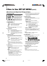
7 REMOTE SYSTEM
Sets the MAKE/TRIGGER terminal.
☞ “How to Use the MAKE/TRIGGER Terminal” on pages
18 and 19
• CONTROL FORM:
Selects the control system for the MAKE/
TRIGGER terminal.
MAKE: Selects the make contact system as
the external control method.
TRIG.: Selects the trigger system as the
external control method.
SET: You can apply the functions to the 1st
to 6th pin terminals of the MAKE/
TRIGGER terminal as you want.
• PORT F1 – PORT F6:
Selects the function to be applied to the 1st to 6th
pin terminals of the MAKE/TRIGGER terminal.
☞ “How to Use the MAKE/TRIGGER Terminal” on page
18
NOTE:
•You can set “PORT F1” – “PORT F6” only when
“CONTROL FORM” is set to “SET.”
7 E. AUDIO GROUP
Sets the group of the available audio output modes
selected by the MENU control.
1G:
2G:
1-2G:
• When SD SDI signal (including EMBEDDED
AUDIO signal) is input, you can select the channel
of the audio signal output from the audio output
terminal by changing the audio output mode.
☞ “6 Audio output terminals” on page 7
7 HOUR METER X100h
Displays the total usage time of the monitor in
hundred-hour units.
• 000 O 655
NOTES:
• When the timer passes 655, it returns to 000.
• The timer does not count usage time under one hour.
EN04_LCT1993-001A-f.p65 06.1.5, 18:2414