


6
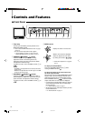
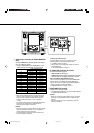
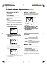
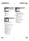
7 Rear Panel
1 Main power switch
Tur ns the main power on and off.
•I : on ⅜ : off
NOTE:
•You need to turn on the stand-by button on the front
panel to turn on the monitor after turning on the main
power switch.
2 AC inlet
Power input connector. Connect the provided AC
power cord to an AC outlet (120 V/220-240 V AC,
50 Hz/60 Hz).
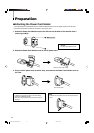
• Attach the provided Power Cord Holder to prevent
accidental disconnection of the AC power cord.
☞ “Attaching the Power Cord Holder” on page 8
3 Composite signal input/output terminals
(VIDEO A, VIDEO B)
Input (IN) and output (OUT) terminals for the
composite signals of the NTSC, PAL, and B/W
(50 Hz/60 Hz).
NOTES:
• NTSC and PAL are switched in the “COLOR SYSTEM.”
☞ “COLOR SYSTEM” on page 14
• The IN and OUT terminals are bridge-connected (auto
termination).
Controls and Features (cont.)
4 External synchronized signal input/output
terminals (for both VIDEO A and VIDEO B)
Input (IN) and output (OUT) terminals for the
composite synchronized signals.
•To use these terminals, set “SYNC SELECT” to
“EXT.”
☞ “SYNC SELECT” on page 14
NOTES:
• When an external synchronized signal is input, external
synchronization is prioritized for both VIDEO A and
VIDEO B.
• The IN and OUT terminals are bridge-connected (auto
termination).
5 REMOTE (external control) terminals
(MAKE/TRIGGER)
Te rminals for controlling the monitor by an external
control.
• Enables the monitor to be controlled by short-
circuiting the pin terminal in this terminal or by
inputting the pulse signal.
☞ “How to Use the External Control” on pages 18 and 19
2
4
5
1
3
EN02_LCT1993-001A-f.p65 06.1.5, 18:256