


H
ARDWARE
R
EFERENCE
G
UIDE
MICRO
-
LINE
C6713CPU
Date : 28 November 2005
Doc. no. : C6713CPU_HRG
Iss./Rev : 1.1
Page : 50
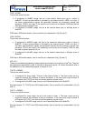
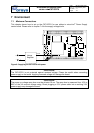
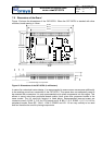
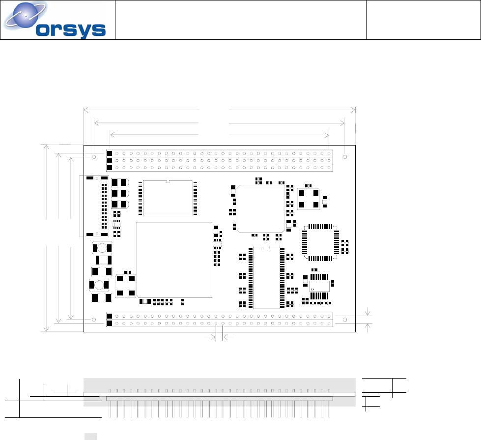
7.9 Dimensions of the Board
Figure 12 shows the dimensions of the C6713CPU. When the C6713CPU is stacked with other
modules, board spacing is 14mm.
C9
78.74
90.17
97.54
58.42
60.96
67.06
2.54
2.54
1,5
1,5
6,0
5,0
3,5
maximum heigh of components
Figure 12: Dimensions of the C6713CPU (in millimeters)
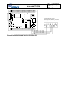
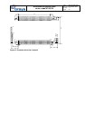
In case of a customized carrier design, it is recommended to reserve some more space additionally
to the existing micro-line
®
connectors of the C6713CPU. This space does not necessarily need to
be mounted with connectors. It is only recommended not to place components into this region. This
allows to mount micro-line
®
peripheral boards and/or future micro-line
®
processor boards in the
same socket. The full micro-line footprint is listed below. Recommended keep-out areas are
connector rows A, B, BB, C, D, E for CPU boards and A, B, BB, C, D, E, EGND 1..4, P, X1..X10 for
peripheral boards. Rows EE, 1394-1, 1394-2, EGND5 and X11..16 are very unlikely to be used
and can therefore be used for placing components.