


MCI_Manual_V13.doc Page: 6 of 20 03555-120
The parameters of the MSR can be set and/or modified
using the corresponding Preh programming software.
You can find further information, as well as the
associated software, in the Internet under
http://www.preh-keytec.com.
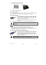
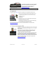
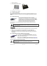
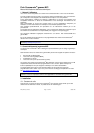
Important notice: Please hold the magnetic card near the upper edge during a swipe.
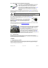
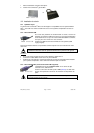
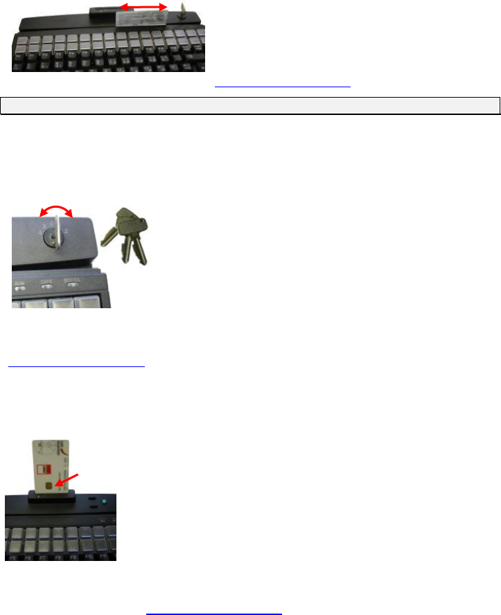
4.2 Keylock (KL)
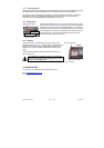
The optional keylock (Figure 8) module has 5 positions and is supplied with 3 different keys.
All keys can be inserted and removed in both positions 0 and 1.
The following switch positions can be set with the three keys:
• SUP key: 0 1 2 3 4
• REG key: 0 1
• X key: 0 1 2
By default, the code for the new switch position is transferred to
the computer when the key is turned.
The parameters of the keylock can be set and/or modified using
the corresponding Preh programming software.
You can find further information, as well as the associated software, in the Internet under
http://www.preh-keytec.com.
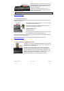
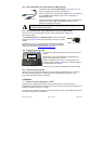
4.3 Smartcard read/write device (SCR)
The EMC 3.1.1- and ISO 7816-certified SCR module of the MCI family
allows you to read and write chip cards of types T=0, T=1, I²C, 2-wire,
3-wire and PTS.
PC/SC drivers for the popular Windows operating systems (as of
Windows 98) are available as the software interface. A CT-API
interface can be placed on the PC/SC interface.
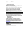
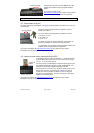
In order to read or write a chip card, carefully insert the chip card into
the read slot; make sure that the chip contact surfaces face in the
direction of the keypad (Figure 9). A slight click indicates that the end
position has been attained. Reading or writing can now be carried out.
You can find further information, as well as the associated driver
software, in the Internet under
http://www.preh-keytec.com.
Fig. 7 Magnetic stripe reader
Swipe direction
Turning direction
Fig. 8 Keylock
Fig. 9 SCR module
Contact-
surfaces