


Hardware Installation 5
KNE24TP/RS User’s Guide - Rev. A01 Kingston Technology Company
Hardware Installation
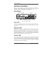
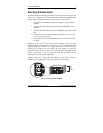
Before you begin installing network cables, please take a few moments to
familiarize yourself with the EtheRx 16-Port and 24-Port Ethernet Hubs. The
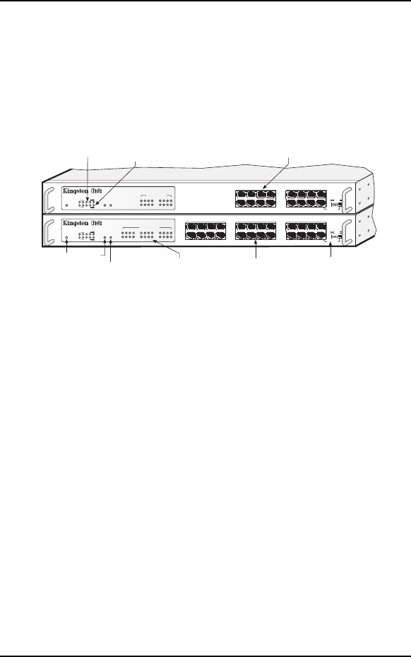
functions on the front and rear panels are illustrated below.
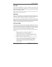
Front Panel
Pro-Series Ethernet Hub
KNE24TP/RS
AUI BNC
3
4
21
PWR
UTIL %
COLL %
LINK / ACT / PARTITION
1 2 3 4 5 6 7 8 9 10 11 12
13 14 15 16 17 18 19 20 21 22 23 24
15
16
1413 19
20
1817
7
8
6511
12
109
21 22 23 24
CASCADE
CABLE TYPE
Pro-Series Ethernet Hub
KNE16TP/RS
AUI BNC
3
4
21
PWR
UTIL %
COLL %
LINK / ACT / PARTITION
1 2 3 4
5 6 7 8
9 10 11 12
13 14 15 16
15
16
1413
7
8
65
11
12
109
CASCADE
CABLE TYPE
UTP Ports
Power
LED
Link /Activity / Partition
LEDs
Cascade Switch
(MDI-X or MDI)
BNC
LED
AUI
LED
Utilization LEDs
UTP Ports
Collision LEDs
Fig. 1. Hub Front Panels
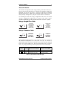
Power LED
The green LED indicates the power status. The LED will light when the AC
power cord is connected from a power source to the hub and the power switch
is turned on.
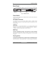
Utilization LEDs
Kingston’s Smart Monitor
™
bar-graph LEDs for utilization and collision
provide easy monitoring of network traffic. There are five Utilization LEDs to
display the amount of network traffic in five percentage levels. The amount of
data traffic is measured in frames per second (FPS), then calculated into the
following percentage forms: 1%, 7%, 15%, 30%, and 60%. The LEDs will
light in a bar-graph fashion based on the network activity.
Collision LEDs
There are five Collision LEDs to display the amount of data packet collisions
in five percentage levels. The amount of data collisions is measured in
collisions per second (CPS), then calculated into the following percentage
levels: 1%, 7%, 15%, 30%, and 60%. The LEDs will light in a bar-graph
fashion based on the amount of collisions.