


6 Hardware Installation
Kingston Technology Company KNE24TP/RS User’s Guide - Rev. A01
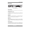
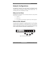
AUI LED
The two-color LED displays two states of operation for the Activity and
Partition status on the AUI port. When data is received, the LED will flash
green. If the port has been partitioned due to excessive collision or other faulty
condition, it will display solid red.
Note: Upon power up, the AUI port LED will not be lit unless a transceiver is
attached to the port and there is activity.
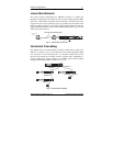
BNC LED
The two-color LED displays the Activity and Partition status on the BNC port.
When data is received, the LED will flash green. If the port is partitioned due
to excessive collision or other faulty condition, it will display solid red.
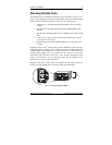
Note: Upon power up, if the BNC port has no cable attached or is not properly
terminated at both ends, the LED will display red to show the port has been
partitioned. Upon receipt of good packets, the LED will automatically change
from red to green indicating that the port is functioning properly.
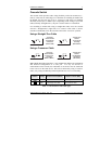
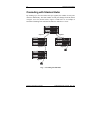
UTP Port LEDs
The sixteen or twenty-four UTP Port LEDs offer condition status for Link,
Activity, and Partition. If a good link is established on any given port, the
green LED will be continuously lit, indicating a valid network connection
between the network node and the hub. When data is received, the LED will
flash green. If the port is partitioned, the LED will display solid red.
If the LED does not display solid green indicating a good link, check the
following:
1. Make sure the power is turned on for both the PC
and EtheRx Hub. The power LED should be lit.
2. Verify the network drivers have been loaded from the PC. Some
adapters require the drivers to be loaded to establish a proper link.
3. Make sure the correct cable type is selected.
4. Make sure the cable is wired properly and connected on both ends.
5. If steps 1, 2, 3, and 4 are correct, the cable may be defective or
not wired correctly. Replace the cable and try again. Please
refer to Appendix A for pin assignments and Appendix B for
cabling guidelines.