


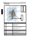

IMAGE STABILIZATION CONTROL CF5001 Ver.1.0 Sep. 2003
2-68
II UNIT EXPLANATION
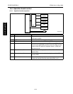
14.4 Dot diameter adjustment control
The dot diameter adjustment control is a method by which intermediate exposure potential is output stably,
regardless of the changes in the sensitivity of photosensitive materials or the stain of the writing system.
The laser output is controlled by the printer control board (PRCB) so that the intermediate exposure poten-
tial that is determined by the PWM128 value for each color is between a developing bias value determined
by the Dmax control and a maximum exposure potential.
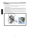
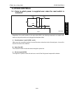
A. Explanation of the operation
The drum potential exposed with a PWM128 value is read by the drum potential sensor and the MPC value
for the laser is corrected to be within the standard value.
B. Timing of the operation
• When the main switch (SW2) is turned on for the first time in 6 hours or more after it was turned off.
• When the job starts 6 hours or more after the SW2 has been turned on.
• Every 1,000 pages of output. However at the time of completion of the job, when the 1,000th page is
contained in the job.
• When the humidity has changed more than 30% RH from the value measured at the last operation.
• When the job starts where the process speed gets slow down to 1/2 or 1/3 speed. However, once
operated under this condition after the SW2 turns on, the operation is not carried out under this condi-
tion until the SW2 turns off.
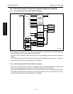
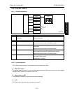
14.5 Gamma correction control
The gamma correction control detects the gamma characteristics of the image density against the expo-
sure amount in the image creation section (drum and transfer belt) for each color, to make the relationship
between the original density and the copy density become the set one.
The gamma correction control is carried out by the gamma sensor (PS11), drum motors /Y, /M, /C and /K
(M14, M15, M16 and M17), transfer belt motor (m18), 1st transfer pressure/release motor (M19) and the
developing motors /Y, /M, /C and /K (M20, M21, M22 and M23), and controlled by the printer control board
(PRCB). Related boards and sensors include the drum potential sensor boards /Y, /M, /C and /K (DRPSB
Y, M, C and K), drum potential sensor /Y, /M, /C and /K (DRPS Y, M, C and K) and the temperature/humid-
ity sensor (TEMP/HUM).
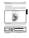
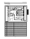
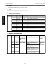
A. Explanation of the operation
The gradation patch is created on the transfer belt and read by the gamma sensor (PS11). The correction
value for the gamma curve is determined by the sensor output value with the predefined relationship
between the sensor output and the output image.
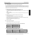
B. Timing of the operation
• When the main switch (SW2) is turned on for the first time in 6 hours or more after it was turned off.
• When the job starts 6 hours or more after the SW2 has been turned on.
• Every 1,000 pages of output. However at the time of completion of the job, when the 1,000th page is
contained in the job.
• When the humidity has changed more than 30% RH from the value measured at the last operation.
• When the job starts where the process speed gets slow down to 1/2 or 1/3 speed. However, once
operated under this condition after the SW2 turns on, the operation is not carried out again until the
SW2 turns off.