


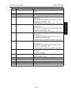

CF5001 Ver.1.0 Sep. 2003 TRANSFER BELT UNIT
2-29
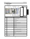
II UNIT EXPLANATION
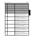
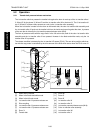
[9] Toner guide brush Scraping and collection of toner on the transfer belt
[10] Toner collection screw Conveys toner from the belt cleaning section to the toner collec-
tion section
Screw method
[11] Image correction unit Detection of variety of information of images transferred on the
transfer belt
[12] Transfer belt separation claw Paper separation assist from the transfer belt
Pressure/release method by the transfer belt separation claw sole-
noid (SD1)
[13] 2nd transfer roller /U Toner transfer from the transfer belt to paper
Constant current DC bias applied roller method
DC output range by constant current method: +30 to -120 µA
[14] 2nd transfer roller /L
(Provided on ADU side)
Toner transfer from the transfer belt to paper
Pressure/release mechanism by means of cam
Driven idly by the transfer belt
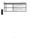
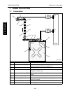
M18 Transfer belt motor Driving of the transfer belt
DC brushless motor, PLL control
M19 1st transfer pressure/release
motor
Pressure/release of the 1st transfer roller /Y, /M, /C, /K
Stepping motor
SD1 Transfer belt separation claw
solenoid
Pressure/release of the separation claw
24 VDC drive
PS15 1st transfer HP sensor
Pressure/release mechanism of the 1st transfer roller /Y, /M, /C, /K
Home position detection
PS68 Encoder sensor/belt 1 Detection of the rotation of encoder for the transfer belt drive shaft
Drive control of the transfer belt motor (M18)
2 sensors of the PS68 and PS69 are provided at the opposite
position of the encoder to cancel the change of rotation caused by
the eccentricity of the encoder.
PS69 Encoder sensor/belt 2 Detection of the rotation of encoder for the transfer belt drive shaft
Drive control of the transfer belt motor (M18)
2 sensors of the PS68 and PS69 are provided at the opposite
position of the encoder to cancel the change of rotation caused by
the eccentricity of the encoder.
Symbol Name Function or method