


CF5001 Ver.1.0 Sep. 2003 DRUM UNIT
2-19
II UNIT EXPLANATION
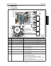
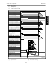
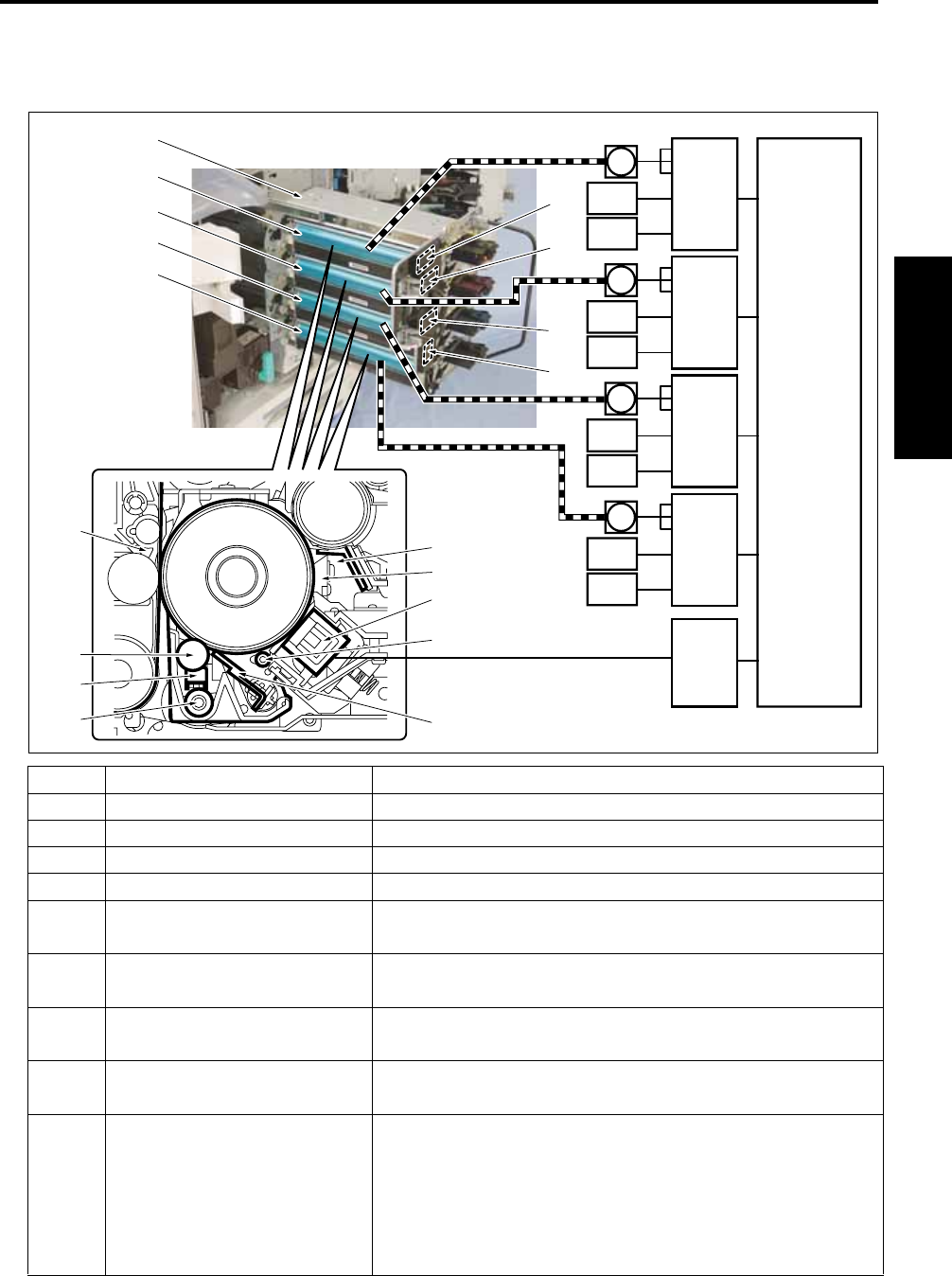
3. DRUM UNIT
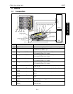
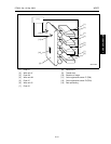
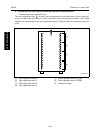
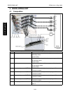
3.1 Composition
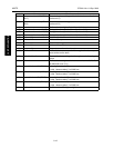
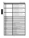
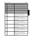
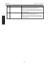
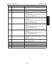
Symbol Name Function or method
[1]
Drum potential sensor board /Y (DRPSB Y)
Controls the drum potential sensor /Y (DRPS Y)
[2]
Drum potential sensor board /M (DRPSB M)
Controls the drum potential sensor /M (DRPS M)
[3]
Drum potential sensor board /C (DRPSB C)
Controls the drum potential sensor /C (DRPS C)
[4]
Drum potential sensor board /K (DRPSB K)
Controls the drum potential sensor /K (DRPS K)
[5] Developing unit /Y Deposits yellow toner to the transfer image on the drum /Y
See "4. Developing unit."
[6] Developing unit /M Deposits magenta toner to the transfer image on the drum /M
See "4. Developing unit."
[7] Developing unit /C Deposits cyan toner to the transfer image on the drum /C
See "4. Developing unit."
[8] Developing unit /K Deposits black toner to the transfer image on the drum /K
See "4. Developing unit."
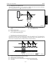
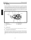
[9] Charging /Y Forms a charging potential on the surface of the drum /Y
DC corona discharge (Scotron)
Wire discharge: gold-plated tungsten wire (φ 30µm)
Constant-current method DC output range: -450 to -1100µA
Grid bias: changing control plate
Constant voltage method DC output range: -200 to -850V
[26]
[25]
[24]
[23]
[22]
[21]
[5]
[1]
[2]
[3]
[4]
[6][7][8]
[9]
[13][14][15][16]
[27][28][29][30]
[10][11][12]
[20]
[19]
[18]
[17]
8050ma2011
U
V
W
1
2
3
1
2
3
1
2
3
M14
M15
PS60
PS61
PS62
PS63
PS64
PS65
PS66
PS67
M16
M17
PRCBHV1
DRDB/K
DRDB/C
DRDB/M
DRDB/Y