


CF5001 Ver.1.0 Sep. 2003 SCANNER
2-1
II UNIT EXPLANATION
II UNIT EXPLANATION
1. SCANNER
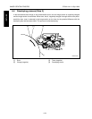
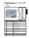
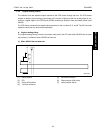
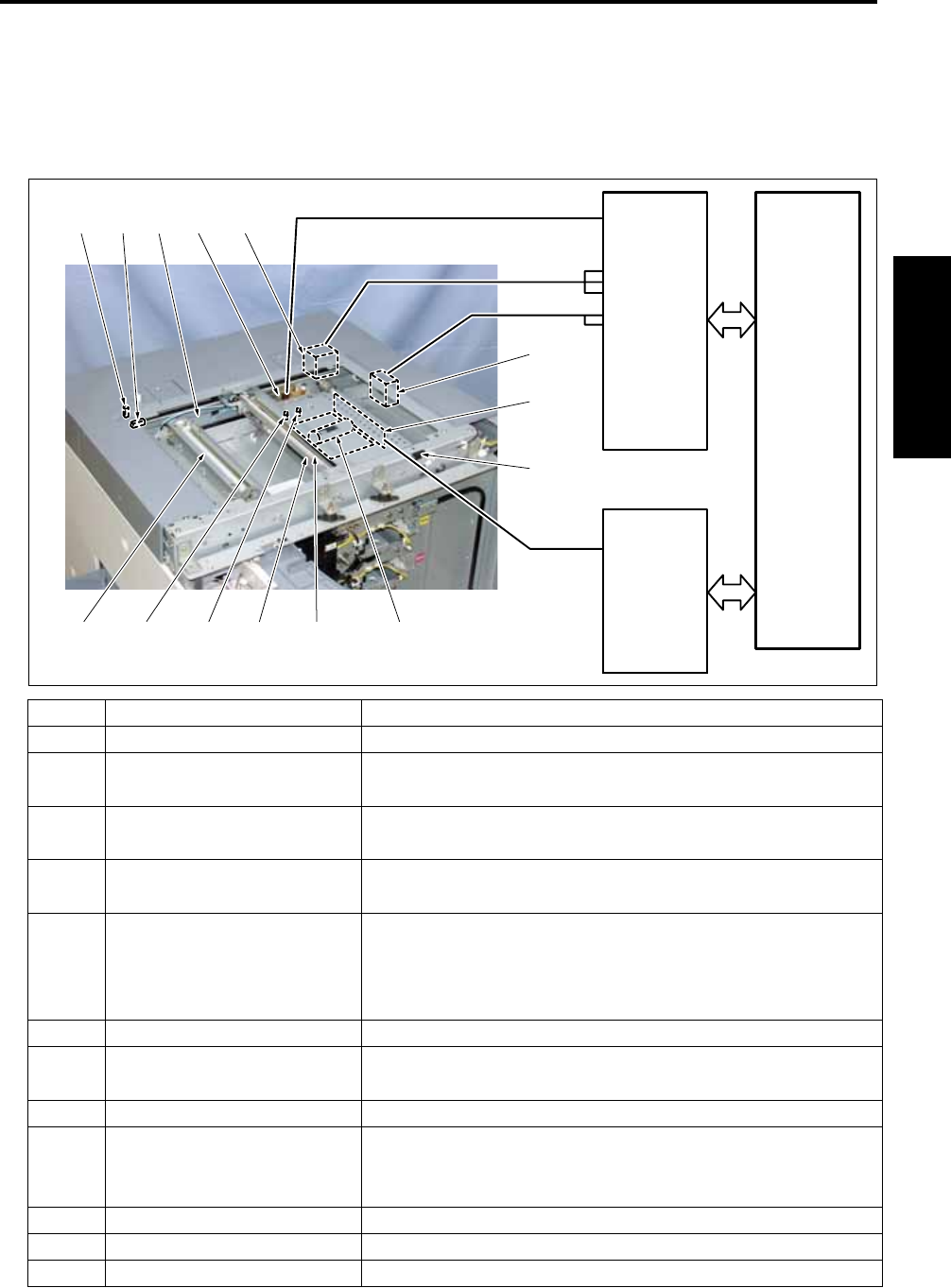
1.1 Composition
Symbol Name Function or method
[1] CCD board (CCDB) Converts an analog signal to a digital signal
[2] DF reset read switch (RS1) Detects whether the platen cover or RADF is closed
Magnet sensor type
[3] CCD unit Converts the read image optoelectronically (600 dpi)
3 lines (RGB) linear image sensor
[4] Exposure lamp (L1) The light source for reading an image
Xenon fluorescent lamp (white)
[5] Exposure unit Reads an image
Light source moving slit exposure
• Outgoing: 220 mm/sec (at life-size)
• Backhaul: 802 mm/sec (at life-size)
[6] V-mirror unit Reflects the read light (2nd, 3rd mirror)
[7] Scanner wire Transfers the driving force from M1 to the exposure unit and the
V-mirror unit (front, back)
[8] L1 inverter (L1 INVB) Turns on L1
M1 Scanner motor Drives the scanner wire for moving the exposure unit and the V-
mirror unit
3-phase stepping motor
M2 Scanner cooling fan Cools the scanner section (exhaust)
PS1 Scanner HP sensor Detects the home position for the exposure unit
PS2 APS timing sensor Detects whether the platen cover or RADF is opened/closed
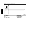
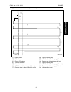
[3][4][5][6]
[7] [8]
[1]
[2]
PS1 PS2
PS4PS3
M1
M2
8050ma2001
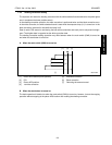
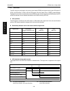
OACB
SCDB
PRCB
CONT
U
V
W
DRIVE
EM