


VP-725NA - Connecting the VP-725NA Presentation Switcher/Scaler 17
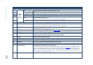
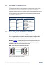
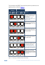
5.2 The RGBS and RGsB Pinouts
The following table defines the input progressive (a display mode in which all the
horizontal lines of an image are displayed in a single frame, one field) and
interlaced (a display mode in which a frame consists of two separate fields with the
first field consisting of odd horizontal lines and the second field even horizontal
lines) RGBS and RGsB pinouts:
RGBS and RGsB Pinouts
Input Color Space PINOUT
VGA RGsB Red to PIN 1
Green + sync, to PIN 2
Blue to PIN 3
RGBS Red to PIN 1
Green to PIN 2
Blue to PIN 3
Hs (H and V) to PIN 13
YUV YPbPr Green + sync to Y
Blue to Pb
Red to Pr
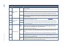
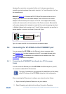
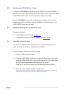
5.3 Connecting to the VP-725NA via RS-232
You can connect to the unit via a crossed RS-232 connection, using for example,
a PC. A crossed cable or null-modem is required as shown in method A and B
respectively. If a shielded cable is used, connect the shield to pin 5.
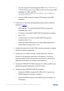
Method A (
Figure 4)—Connect the RS-232 9-pin D-sub port on the unit via a
crossed cable (only pin 2 to pin 3, pin 3 to pin 2, and pin 5 to pin 5 need be
connected) to the RS-232 9-pin D-sub port on the PC.
Note: There is no need to connect any other pins.
Figure 4: Crossed Cable RS-232 Connection
1
2
6
3
7
4
8
5
9
1
2
6
3
7
4
8
5
9
PC