


18 VP-81K - Connecting the VP-81K
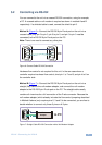
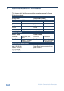
5.5 DIP-Switch Settings
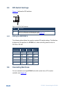
Figure 14 defines the DIP-switches:
(1 2 3)
Figure 14: SETUP DIP-Switches
DIP Function
1-3 Machine #: determines the number of the machine in the sequence
4
ON for RS-485 Line Termination with 120Ω;
OFF for no RS-485 Line Termination (see Section
5.3)
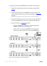
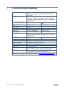
5.5.1 Setting the MACHINE #
The following table defines the machine number DIP-switch settings. The Machine
# determines the position of a VP-81K unit, when controlling several units via
RS-232 or RS-485.
MACHINE # DIP-Switch Settings
MACHINE # DIP 1 DIP 2 DIP 3
1 OFF OFF OFF
2 OFF OFF ON
3 OFF ON OFF
4 OFF ON ON
5 ON OFF OFF
6 ON OFF ON
7 ON ON OFF
8 ON ON ON
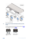
5.6 Cascading Machines
You can cascade up to eight VP-81K units with control from a PC or serial
controller (see Figure 15
).