


VP-81K – Overview 5
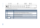
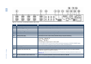
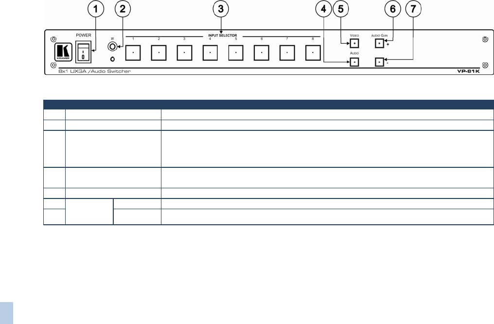
Figure 1: VP-81K 8x1 UXGA/Audio Switcher Front Panel
# Feature Function
1 POWER Switch Illuminated switch supplying power to the unit
2 IR Receiver The yellow LED is illuminated when receiving signals from the Kramer Infrared remote control transmitter
3 INPUT SELECTOR Buttons Select the input (from 1 to 8) to switch to the outputs
The button illuminates in red if it is selected and there is no input signal
The button illuminates in green if it is not selected but there is an input signal at that input
The button illuminates in violet if it is selected and there is an input signal connected
4 AUDIO Button When illuminated, actions relate to audio
If the AUDIO and VIDEO buttons both illuminate, the unit operates in the audio-follow-video mode
5 VIDEO Button When illuminated, actions relate to video
6
AUDIO
GAIN
Buttons
+ Press to increase the audio output level of the selected input (while the AUDIO button illuminates)
7 - Press to decrease the audio output level of the selected input