


VP-81K – Contents i
Contents
1 Introduction 1
2 Getting Started 2
2.1 Achieving the Best Performance 2
3 Overview 3
3.1 DDC Support 4
3.2 Defining EDID 4
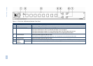
3.3 Defining the VP-81K 8x1 UXGA/Audio Switcher 4
3.4 Using the IR Transmitter 7
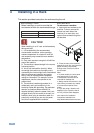
4 Installing in a Rack 8
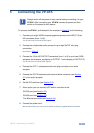
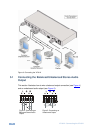
5 Connecting the VP-81K 9
5.1 Connecting the Balanced/Unbalanced Stereo Audio Output 10
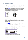
5.2 Controlling via RS-232 11
5.3 Connecting a PC or Controller to the RS-485 Port 12
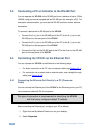
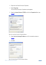
5.4 Controlling the VP-81K via the Ethernet Port 12
5.5 DIP-Switch Settings 18
5.6 Cascading Machines 18
6 Operating Your VP-81K 8x1 UXGA/Audio Switcher 20
6.1 Using the Front Panel Input Selector Buttons 20
6.2 Using the Regular or Automatic Switching Mode 20
6.3 Using the Audio-Follow-Video/Breakaway Modes 21
6.4 Setting the Audio Gain 22
7 Technical Specifications 23
8 Communication Parameters 24
9 Table of ASCII Codes for Serial Communication (Protocol 3000) 25
10 Table of Hex Codes for Serial Communication (Protocol 2000) 26
11 Kramer Protocol 28
11.1 Switching Protocols 28
11.2 Kramer Protocol 3000 29
11.3 Kramer Protocol 2000 36
Figures
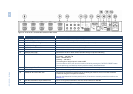
Figure 1: VP-81K 8x1 UXGA/Audio Switcher Front Panel 5
Figure 2: VP-81K 8x1 UXGA/Audio Switcher Rear Panel 6
Figure 3: Connecting the VP-81K 10
Figure 4: Connecting an Balanced Stereo Audio Output 10
Figure 5: Connecting an Unbalanced Output 10
Figure 6: Crossed Cable RS-232 Connection 11
Figure 7: Straight Cable RS-232 Connection with a Null Modem Adapter 11
Figure 8: Local Area Connection Properties Window 13
Figure 9: Internet Protocol (TCP/IP) Properties Window 13
Figure 10: Connect Screen 14
Figure 11: Device Properties Screen 15
Figure 12: HOME Embedded Web Page 16
Figure 13: CONFIGURATIONS Embedded Web Page 17
Figure 14: SETUP DIP-Switches 18
Figure 15: Control Configuration via RS-232 and RS-485 19