


Kramer Protocol 2000
19
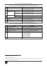
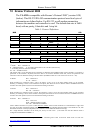
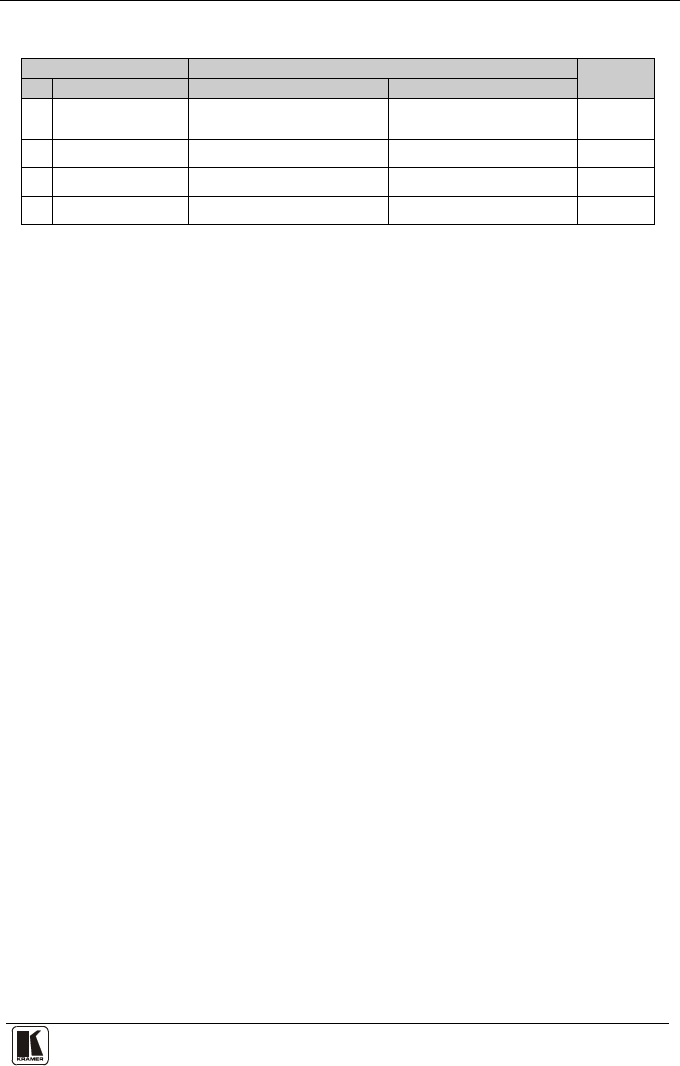
Table 6: Instruction Codes for Protocol 2000
Note: All values in the table are decimal, unless otherwise stated.
INSTRUCTION
DEFINITION FOR SPECIFIC INSTRUCTION
NOTE
#
DESCRIPTION
INPUT
OUTPUT
1 SWITCH VIDEO Set equal to video input which is to
be switched
(0 = disconnect)
Set equal to video output which is
to be switched
(0 = to all the outputs)
2, 15
3 STORE VIDEO
STATUS
Set as SETUP # 0 - to store
1 - to delete
2, 3, 15
4 RECALL VIDEO
STATUS
Set as SETUP # 0 2, 3, 15
30 LOCK FRONT PANEL 0 - Panel unlocked
1 - Panel locked
0 2
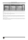
NOTES on the above table:
NOTE 2 - These are bi-directional definitions. That is, if the switcher receives the code, it will perform the instruction; and if
the instruction is performed (due to a keystroke operation on the front panel), then these codes are sent. For example, if the
HEX code
01 85 88 83
was sent from the PC, then the switcher (machine 3) will switch input 5 to output 8. If the user switched input 1 to output 7
via the front panel keypad, then the switcher will send HEX codes:
41 81 87 83
to the PC.
When the PC sends one of the commands in this group to the switcher, then, if the instruction is valid, the switcher replies by
sending to the PC the same four bytes that it was sent (except for the first byte, where the DESTINATION bit is set high).
NOTE 3 - SETUP # 0 is the present setting. SETUP # 1 and higher are the settings saved in the switcher's memory, (i.e. those
used for Store and Recall).
NOTE 15 – When the OVR bit (4
th
byte) is set, then the “video” commands have universal meaning. For example, instruction
1 (SWITCH VIDEO) will cause all units (including audio, data, etc.) to switch. Similarly, if a machine is in “FOLLOW”
mode, it will perform any “video” instruction.