


Pinouts
54
ETS Installation Guide
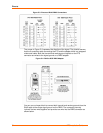
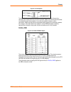
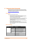
Figure C-3. Pinouts of RJ45-DB25 Connections
The arrows in Figure C-3 represent the direction of the signal. The pinouts assume
that the 8-conductor cable connecting the ETS and the adapter block is a swapped/
rolled serial cable. Both the transmit and receive ground signals on the ETS
connector are wired to the signal ground on a DB25 adapter.
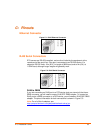
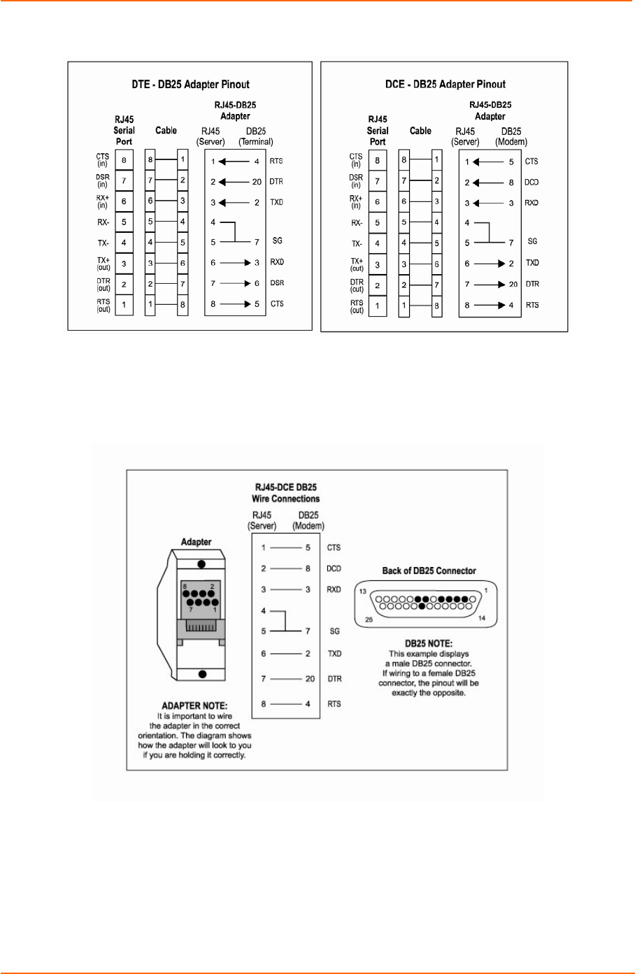
Figure C-4. RJ45 to DCE DB25 Adapter
You can use a crimper block to connect both transmit and receive grounds from the
RJ45 cable to the single signal ground on the DB25. The connector internally
“splices” the two wires together and provides one wire into the DB25 connector as
shown below.