


ETS Installation Guide
9
2
2
:
:
I
I
n
n
s
s
t
t
a
a
l
l
l
l
a
a
t
t
i
i
o
o
n
n
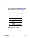
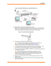
This chapter describes the various ETS models and shows how to install them into a
basic network configuration. The ETSPS models will be explained first. For ETSPR
descriptions and installation instructions, skip to ETSPR Product Descriptions.
ETSP Product Descriptions
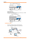
ETSPS Front Panels
The front panel of all ETSP models has a Test/Reset button (called Reset on the
ETS8PS and ETS16PS), seven LEDs, and a power switch. Pressing the Reset
button for 5 seconds while the unit powers up will flush the NVR (factory reset).
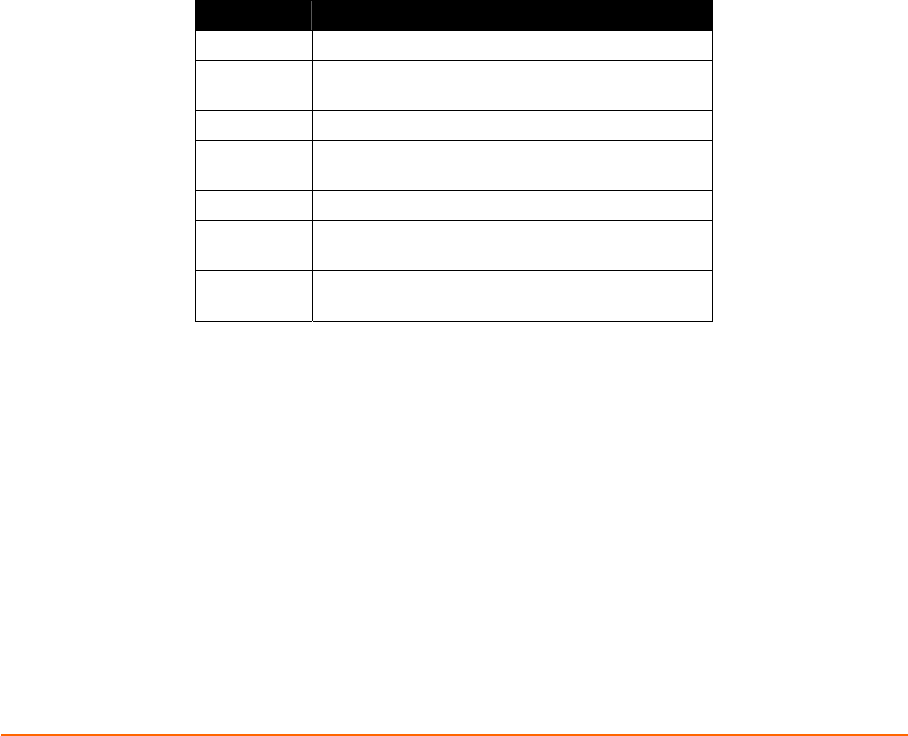
ETS8PS/ETS16PS LEDs
The seven LEDs are explained in the following table.
Table 2-1. ETS8PS/ETS16PS LED Functionality
LED Function
PWR Lights to indicate the ETS has power
LNK
Lights to indicate a functional 10BASE-T
network link
POL Lights to indicate a swapped 10BASE-T cable
OK
Blinks to indicate that the ETS is functioning
properly
NET Blinks to indicate Ethernet activity
RCV
Blinks periodically to indicate serial characters
entering the ETS
XMT
Blinks periodically to indicate serial characters
exiting the ETS
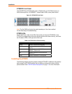
ETS8PS Back Panel
The back panel of the ETS8PS has a power plug, an AUI Ethernet port, an RJ45
10BASE-T Ethernet port, and eight RJ45 serial ports.