


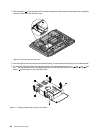
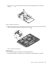
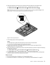
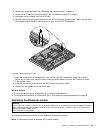
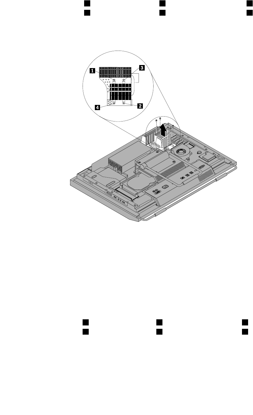
6. Follow this sequence to remove the four screws that secure the heat sink to the system board:
a. Partially remove screw 1 , then fully remove screw 2 , and then fully remove screw 1 .
b. Partially remove screw 3 , then fully remove screw 4 , and then fully remove screw 3 .
Note: Carefully remove the four screws from the system board to avoid any possible damage to the
system board. The four screws cannot be removed from the heat sink.
Figure23. Removing the heat sink
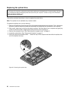
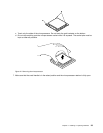
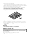
7. Lift the failing heat sink off the system board.
Notes:
a. You might have to gently twist the heat sink to free it from the microprocessor.
b. Do not touch the thermal grease while handling the heat sink.
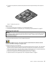
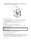
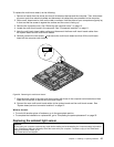
8. Position the new heat sink on the system board so that the four screws are aligned with the
corresponding holes in the system board.
9. Follow this sequence to install the four screws to secure the heat sink, as shown in Figure 23 “Removing
the heat sink” on page 31.
a. Partially tighten screw 1 , then fully tighten screw 2 , and then fully tighten screw 1 .
b. Partially tighten screw 3 , then fully tighten screw 4 , and then fully tighten screw 3 .
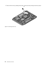
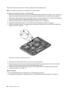
10. To reinstall the fan duct, position the fan duct on the heat sink and then press the fan duct downward
until the two tabs on the fan duct are secured into place.
What to do next:
• To work with another piece of hardware, go to the appropriate section.
• To complete the installation or replacement, go to “Completing the parts replacement” on page 52.
Chapter 2. Installing or replacing hardware 31