


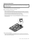
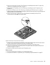
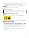
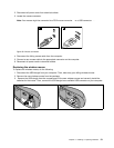
7. To install the new right I/O assembly into the computer, position the new right I/O assembly into place
and then align the screw holes with the corresponding holes in the computer main bracket.
8. Install the three screws to secure the right I/O assembly to the computer main bracket.
9. Connect the right I/O assembly cable and the intrusion switch cable to the new right I/O assembly.
What to do next:
• To work with another piece of hardware, go to the appropriate section.
• To complete the installation or replacement, go to “Completing the parts replacement” on page 52.
Replacing the power supply
Attention:
Do not open your computer or attempt any repair before reading and understanding the “Important safety information”
in the ThinkCentre Safety and Warranty Guide that came with your computer. To obtain a copy of the ThinkCentre
Safety and Warranty Guide, go to:
http://www.lenovo.com/support
This section provides instructions on how to replace the power supply.
CAUTION:
Never remove the cover on a power supply or any part that has the following label attached.
Hazardous voltage, current, and energy levels are present inside any component that has this label
attached. There are no serviceable parts inside these components. If you suspect a problem with
one of these parts, contact a service technician.
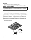
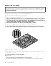
To replace the power supply, do the following:
1. Remove all media from the drives and turn off all attached devices and the computer. Then, disconnect
all power cords from electrical outlets and disconnect all cables that are connected to the computer.
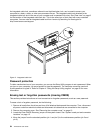
2. Place a soft, clean towel or cloth on the desk or surface. Hold the sides of your computer and gently lay
it down so that the screen is against the surface and the cover is facing up.
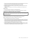
3. Remove the computer cover. See “Removing the computer cover” on page 15.
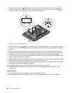
4. Disconnect the power supply cable from the system board. See “System board part and connector
locations” on page 12.
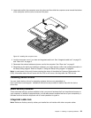
5. Remove the hard disk drive. See “Replacing the hard disk drive” on page 25.
6. Remove the rear I/O assembly cover. See “Removing or reinstalling the rear I/O assembly cover”
on page 19.
Chapter 2. Installing or replacing hardware 47