


4. Remove the frame stand or lift stand. See “Removing or reinstalling the frame stand” on page 16 or
“Removing or reinstalling the lift stand” on page 17.
5. Remove the rear I/O assembly cover. See “Removing or reinstalling the rear I/O assembly cover”
on page 19.
6. Remove the VESA frame cover. See “Removing or reinstalling the VESA frame cover” on page 20.
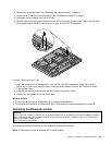
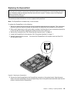
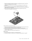
7. Note the routing of the microprocessor fan assembly cable and then disconnect the microprocessor fan
assembly cable from the system board.
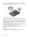
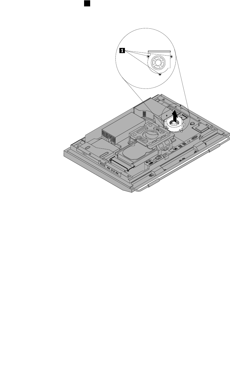
8. Remove the three screws 1 that secure the microprocessor fan assembly and then lift the
microprocessor fan assembly off the system board.
Figure33. Removing the microprocessor fan assembly
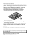
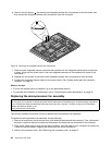
9. Position the new microprocessor fan assembly on the system board and align the three screw holes in
the new microprocessor fan assembly with those in the system board.
10. Install the three screws to secure the microprocessor fan assembly to the system board.
11. Connect the microprocessor fan assembly cable to the system board. See “System board part and
connector locations” on page 12.
12. Reinstall the VESA frame cover and the rear I/O assembly cover.
What to do next:
• To work with another piece of hardware, go to the appropriate section.
• To complete the installation or replacement, go to “Completing the parts replacement” on page 52.
Chapter 2. Installing or replacing hardware 43