


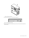
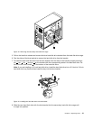
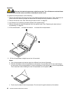
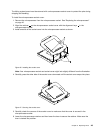
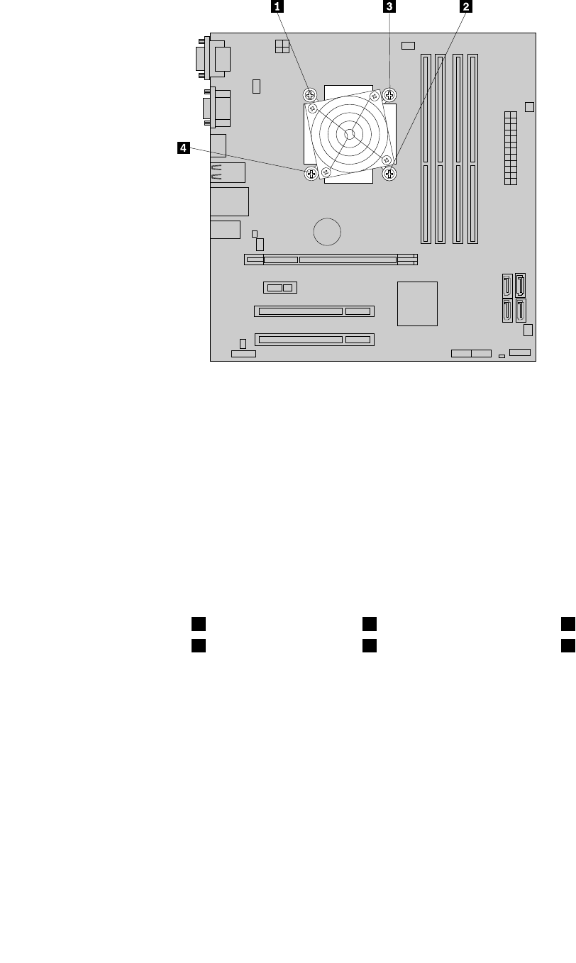
Figure 23. Removing the heat sink and fan assembly
7. Lift the failing heat sink and fan assembly off the system board.
Notes:
a. You might have to gently twist the heat sink and fan assembly to free it from the microprocessor.
b. When handling the heat sink and fan assembly, do not touch the thermal grease on the bottom
of the heat sink and fan assembly.
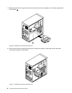
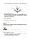
8. Position the new heat sink and fan assembly on the system board so that the four screws are aligned
with the corresponding holes in the system board. Make sure that the heat sink and fan assembly cable
can be easily connected to the microprocessor fan connector on the system board.
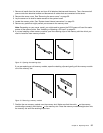
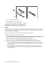
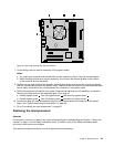
9. Follow this sequence to install the four screws to secure the heat sink and fan assembly, as shown in
Removing the heat sink and fan assemblyFigure 23 on page 45.
a. Partially tighten screw 1 , then fully tighten screw 2 , and then fully tighten screw 1 .
b. Partially tighten screw 3 , then fully tighten screw 4 , and then fully tighten screw 3 .
10. Connect the heat sink and fan assembly cable to the microprocessor fan connector on the system
board. See “System-board internal connectors” on page 25.
11. Go to “Completing the parts replacement” on page 57.
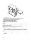
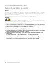
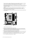
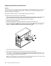
Replacing the microprocessor
Attention
Do not open your server or attempt any repair before reading and understanding the Chapter 1 “About this
manual” on page 1 and the Safety Information book. To obtain a copy of the Safety Information book,
go to:http://www.lenovo.com/support
This section provides instructions on how to replace the microprocessor.
Chapter 6. Replacing FRUs 45