Chapter 3. Server controls, LEDs, and power
This section describes the controls and light-emitting diodes (LEDs) and how to turn
the server on and off.
Front view
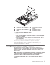
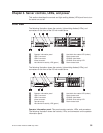
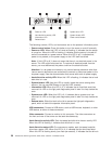
The following illustration shows the controls, light-emitting diodes (LEDs), and
connectors on the front of the 3.5-inch model server.
1 Operator information panel 6 Hard disk drive status LED (amber)
2 USB 5 connector 7 Rack release latch
3 USB 6 connector 8 CD/DVD eject button
4 Video connector 9 CD/DVD drive activity LED
5 Hard disk drive activity LED (green) 10 Rack release latch
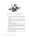
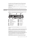
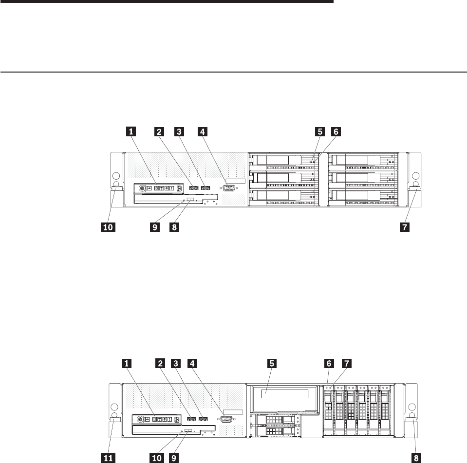
The following illustration shows the controls, light-emitting diodes (LEDs), and
connectors on the front of the 2.5-inch model server.
1 Operator information panel 7 Hard disk drive status LED (amber)
2 USB 5 connector 8 Rack release latch
3 USB 6 connector 9 CD/DVD eject button
4 Video connector 10 CD/DVD drive activity LED
5 Tape drive bay 11 Rack release latch
6 Hard disk drive activity LED (green)
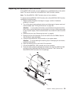
Operator information panel: This panel contains controls, LEDs, and connectors.
The following illustration shows the controls, LEDs, and connectors on the operator
information panel.
© Lenovo 2008. Portions © IBM Corp. 2007. 35


