


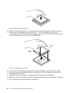
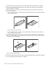
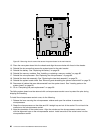
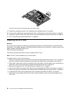

Figure32. Removing the six screws that secure the system board to the main bracket
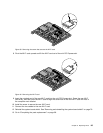
13. Place the new system board into the chassis and align the screw holes with those in the chassis.
14. Reinstall the six screws that secure the system board to the main bracket.
15. Reinstall the battery. See “Replacing the battery” on page 83.
16. Reinstall the memory modules. See “Installing or replacing a memory module” on page 85.
17. Reinstall the microprocessor. See “Replacing the microprocessor” on page 80.
18. Reinstall the heat sink assembly. See “Replacing the heat sink assembly” on page 78.
19. Reinstall the system board shield. See “Removing and reinstalling the system board shield” on page 76.
20. Reconnect all cables that were disconnected from the system board. See “Locating parts on the
system board” on page 66.
21. Go to “Completing the parts replacement” on page 96.
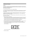
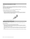
The failing system board must be returned with a microprocessor socket cover to protect the pins during
shipping and handling.
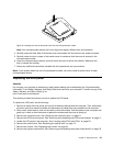
To install the microprocessor socket cover, do the following:
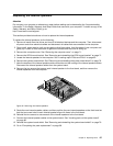
1. Release the lever securing the microprocessor retainer and open the retainer to access the
microprocessor.
2. Grasp the microprocessor on the sides and lift it straight up and out of the socket. Do not touch the
contacts on the microprocessor socket.
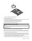
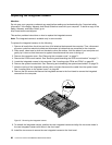
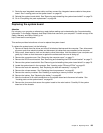
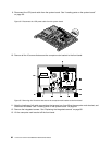
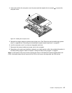
3. Note the orientation of the socket cover. Align the notches on the microprocessor socket cover
with the alignment keys on the microprocessor socket. Install one side of the socket cover into the
microprocessor socket.
90 Lenovo S710 All-In-OneHardware Maintenance Manual