


54
IdeaPad Y560 Hardware Maintenance Manual
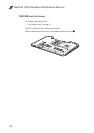
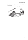
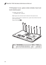
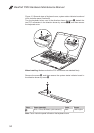
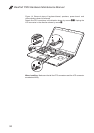
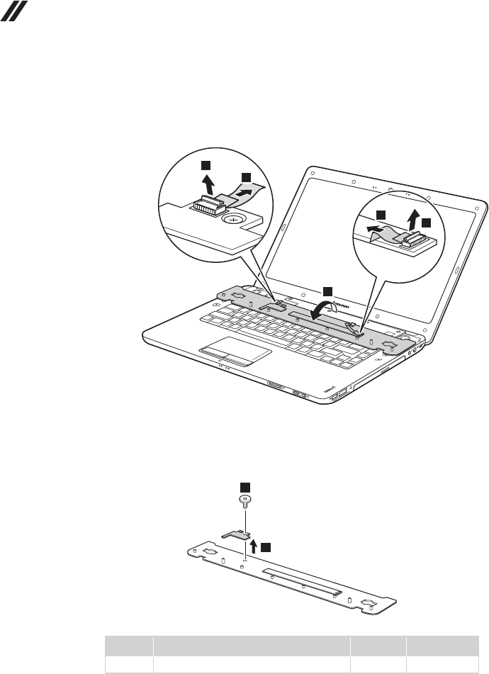
Figure 12. Removal steps of keyboard cover, system status indicator board and
touch inductive panel (continued)
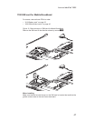
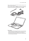
Turn the keyboard cover over in the direction shown by arrow
5
, detach the
two FPC connectors in the direction shown by arrows
6
7
, and then remove
the keyboard cover.
5
6
7
6
7
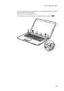
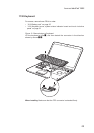
When installing: Make sure that the FPC connectors are attached rmly.
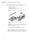
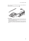
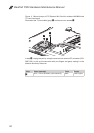
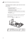
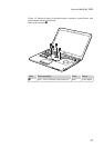
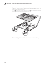
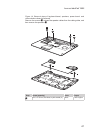
Remove the screw
8
, and then remove the system status indicator board in
the direction shown by arrow
9
.
9
8
Step Screw (quantity) Color Torque
8
M2.5 × 2 mm, at-head, nylok-coated (1) Black 1.5±0.2 kgfcm
Note: Touch inductive panel is xed on the keyboard cover.