


4076-0XX
40
To install the left side frame onto the middle frame, align the right
side frame latch with the latching surface on the middle frame before
you align the roller shafts and carrier guide. It may be easier to do
this with the machine on its right side.
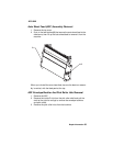
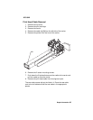
Maintenance Drive And Rocker Assemblies Removal
1. Remove the top cover.
2. Remove the auto sheet feed.
3. Remove the right side frame.
4. Gently unlatch the maintenance assembly latches, and slide out
the maintenance drive assembly, then the rocker assembly.
When you reassemble the drive assembly, be sure the forks engage
the pins on the rocker assembly.
Middle Frame Removal
1. Remove the top cover.
2. Remove the print cartridge.
3. Remove the auto sheet feed.
4. Disconnect the print head cables from the system board. You
may have to open the print head cable connectors on the system
board first, then disconnect the cables.
5. Disconnect J4, J5, and J6 from the system board.
6. Remove the machine from the base. To do this, unlatch the 4
base frame latches. Lift the machine from the base and set it
aside.
7. Remove the paper ejectors from the middle frame.
8. Remove the left side frame.
9. Remove the exit shaft.
10. Remove the small feed roller shaft.
11. Remove the large feed roller shaft and springs.
12. Remove the end-of-forms flag.
13. Remove the right side frame.
14. Remove the maintenance station.
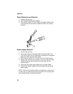
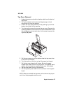
Operator Panel Removal
1. Remove the top cover.
2. Remove the 3 operator panel mounting screws.
3. Remove the operator panel.