


4026-0XX
Diagnostic Information 2-23
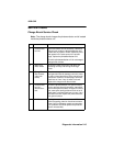
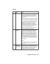
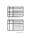
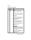
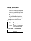
Post Incomplete - ERROR LED remains on solid
Note: Be sure the top cover is closed when doing the following
checks.
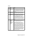
5
ROM SIMM
and Optional
Memory
SIMM
Reinstall the ROM SIMM. Check for +5 V dc at
CN7-4. If incorrect, replace the ROM SIMM.
Reinstall the optional memory SIMM if one was
installed. Check for +5 V dc at CN7-4. If incor-
rect, replace the optional memory SIMM.
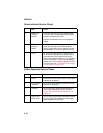
6
HVPS Reconnect CN4 and check for +5 V dc at CN7-
4. If incorrect, replace the HVPS.
7
Printhead
Assembly
Reconnect CN5 and CN10. Check for +5 V dc at
CN7-4. If incorrect, replace the printhead
assembly.
8
Thermistor Reconnect CN2 and check for +5 V dc at CN7-
4. If incorrect, replace the thermistor/cable
assembly.
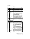
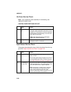
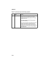
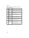
FRU Action
1
LVPS Disconnect the LVPS cable from the engine
board. Thevoltage measures approximately +24
V dc between pin 1 (+24 V dc) and pin 2 (+24 V
dc ground). If incorrect, replace the LVPS.
2
Engine Board Reconnect the LVPS cable and measure the
voltage on CN7-1. The reading should measure
approximately +24 V dc. If incorrect, disconnect
CN3, CN4, CN6, CN9, CN10 and CN11 from the
engine board. The voltage on CN7-1 measures
+24 V dc. If incorrect, replace the engine board.
If correct, reconnect one cable at a time check-
ing the voltage at CN7-1 until the FRU causing
the problem is found. Replace the failing FRU.
If the CN3 or CN9 are causing the problem, it is
necessary to disconnect each solenoid and
check the voltage at CN7-1. Replace the failing
FRU.
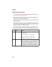
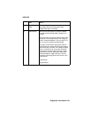
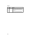
FRU Action