


8 Plasma Monitor
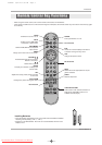
Introduction
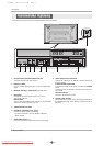
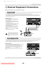
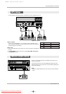
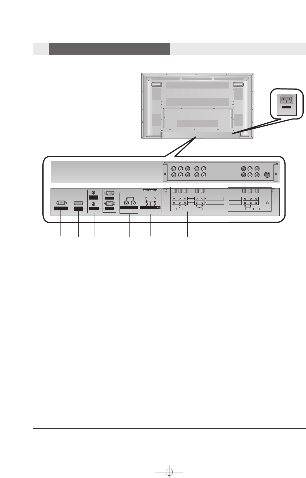
- Connection panels shown may be somewhat different from your Monitor.
AC INPUT
RS-232C INPUT
(CONTROL/SERVICE)
AUDIO
AUDIO
LR
REMOTE
CONTROL
AUDIO INPUT
RGB INPUT
HDMI/
DVI(VIDEO)
RGB OUTPUT
S-VIDEO
COMPONENT INPUT 2
COMPONENT INPUT 1
AUDIO
VIDEO
RL
AUDIO
VIDEO
R
MONITOR OUTPUT
A/V INPUT
L
(MONO)
EXTERNAL SPEAKER
R
L
VARIABLE AUDIO OUT
1
5
2 3
7
8
9
1. RS-232C INPUT(CONTROL/SERVICE) PORT
Connect to the RS-232C port on a PC.
2. HDMI/DVI (VIDEO)
Connect a HDMI signal to this jack. Or connect a DVI(Video)
signal.
3. REMOTE CONTROL / AUDIO INPUT (for RGB, DVI)
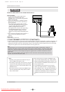
4. RGB INPUT
Connect the set output connector from a PC to the
appropriate input port.
RGB OUTPUT
You can watch the RGB signal on another set, connect RGB
OUTPUT to another set’s PC input port.
5. VARIABLE AUDIO OUTPUT
6. EXTERNAL SPEAKER (8 ohm output)
Connect to optional external speaker(s).
* For further information, refer to ‘Speaker & Speaker
Stand’ manual.
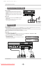
7. COMPONENT INPUT 1-2
Connect a component video/audio device to these jacks.
8. VIDEO/AUDIO IN/OUT SOCKETS
Connect the video/audio out sockets of external equipment
to these sockets.
S-VIDEO/AUDIO IN SOCKETS
Connect the S-VIDEO out socket of an VCR to the S-VIDEO
socket.
Connect the audio out sockets of the VCR to the audio sock-
ets as in AV.
MONITOR OUTPUT
Connect a second Set or monitor.
9. POWER CORD SOCKET
This set operates on an AC power. The voltage is indicated on
the Specifications page. Never attempt to operate the set on
DC power.
4
6
Connection Options
Connection Options
U514Aen 98/2/18 4:25 AM Page 8
Downloaded From TV-Manual.com Manuals