28 Wiring Inspection
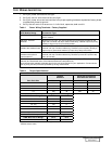
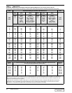
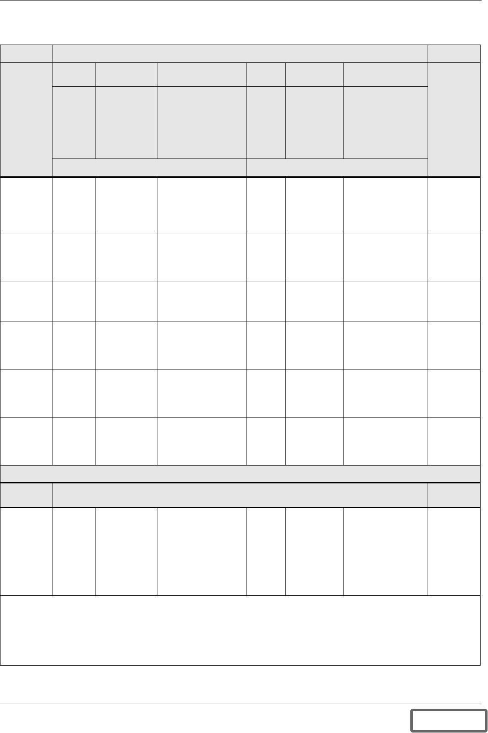
Tab le 3 Table 310-16
Allowable Ampacities of Insulated Conductors Rated 0-2000 Volts, 60° to 90°C (140° to 194°F)
1
Not More than Three Conductors in Raceway or Cable or Earth (Directly Buried), based on Ambient Temperature of 30° (86°F)
Size Temperature Rating of Conductor. See T able 310-13. Size
AWG
kcmil
60°C
(140°F)
75°C
(167°F)
90°C
(194°F)
60°C
(140°F)
75°C
(167°F)
90°C
(194°F)
AWG
kcmil
Types
TW*
UF*
Types
FEPW*,
RH, RHW*,
THHW*,
THW*,
THWN*,
XHHW*,
USE*, ZW*
Types
TBS, SA, SIS
FE P*, FEPB*, MI,
RHH*, RHW-2,
THHN*, THHW*,
THW-2, THWN-2,
USE-2, XHH, XHHW*
XHHW-2, ZW-2
Types
TW*
UF*
Types
RH*, RHW*,
THHW*,
THW*,
THWN*,
XHHW*,
USE*
Types
TBS, SA, SIS,
THHN*, THHW*,
THW-2, THWN-2,
RHH*, RHW-2,
USE-2,
XHH, XHHW*,
XHHW-2, ZW-2
Copper Alum inum or Copper-Clad Aluminum
18
16
14
12
10
8
.......
.......
20†
25†
30
40
.......
.......
20†
25†
35†
50
14
18
25†
30†
40†
55
.......
.......
.......
20†
25
30
.......
.......
.......
20†
30†
40
.......
.......
.......
25†
35†
45
.......
.......
.......
12
10
8
6
4
3
2
1
55
70
85
95
110
65
85
100
115
130
75
95
110
130
150
40
55
65
75
85
50
65
75
90
100
60
75
85
100
115
6
4
3
2
1
1/0
2/0
3/0
4/0
125
145
165
195
150
175
200
230
170
195
225
260
100
115
130
150
120
135
155
180
135
150
175
205
1/0
2/0
3/0
4/0
250
300
350
400
500
215
240
260
280
320
255
285
310
335
380
290
320
350
380
430
170
190
210
225
260
205
230
250
270
310
230
255
280
305
350
250
300
350
400
500
600
700
750
800
900
355
385
400
410
435
420
460
475
490
520
475
520
535
555
585
285
310
320
330
355
340
375
385
395
425
385
420
435
450
480
600
700
750
800
900
1000
1250
1500
1750
2000
455
495
520
545
560
545
590
625
650
665
615
665
705
735
750
375
405
435
455
470
445
485
520
545
560
500
545
585
615
630
1000
1250
1500
1750
2000
Correction Factors
Ambient
Temp °C
For ambient temperatures other than 30°C (86°F), multiply the allowable ampacities shown
above by the appropriate factor shown below.
Ambient
Temp °F
21-25
26-30
31-35
36-40
41-45
46-50
51-55
56-60
61-70
71-80
1.08
1.00
.91
.82
.71
.58
.41
.......
.......
.......
1.05
1.00
.94
.88
.82
.75
.67
.58
.33
.......
1.04
1.00
.96
.91
.87
.82
.76
.71
.58
.41
1.08
1.00
.91
.82
.71
.58
.41
.......
.......
.......
1.05
1.00
.94
.88
.82
.75
.67
.58
.33
.......
1.04
1.00
.96
.91
.87
.82
.76
.71
.58
.41
70-77
78-86
87-95
96-104
105-113
114-122
123-131
132-140
141-158
159-176
* Unless otherwise specifically per mitted elsew here in this Code, the overcurrent protection for conductor types marked with an
asterisk (*) shall not exceed 15 amperes for No. 14, 20 amperes for No. 12, and 30 amperes for No. 10 copper; or 15 amperes for
No.12 an d 25 amperes for No. 10 aluminum and copper-c lad aluminum after any correction factors for ambient temp erature and
number of conductors have been applied.
1
Reprinted with perm i ssion from NEC 1999, NFPA 70, the National Electrical Code®, Copyright 1998, Nation al Fire Protection
Association, Quincy, MA 02269. This reprinted material is not the complete and official position of the National Fire Protection
Association, on the referenced subject whi ch is represented only by the standard in its enti rety.
DISCONTINUED
PRODUCT


