Glycol/GLYCOOL-Cooled Models
28
5.4 Glycol Piping
NOTICE
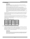
Galvanized pipe must not be used in or with systems or units that contain glycol. The
phosphates in the inhibitor can react with the zinc in the galvanized pipe, precipitating an
insoluble material that can eventually foul the system.
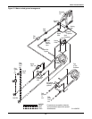
To help prevent piping failures, supply and return lines must be supported in a way that
keeps their weight from bearing on the piping of the unit, drycooler or pumps.
To avoid the possibility of burst pipes, it is necessary to install a relief valve in the system.
This valve may be obtained from the supplier as an option or obtained from another vendor.
Fluid-cooled condensers have small internal flow passages. To avoid clogging and other
resulting system operation problems, install a 16-20 mesh filter in the fluid supply line to the
indoor unit. The filter should be located where it can be easily serviced or replaced.
Do not install unit on open-loop systems. Debris carried by the fluid will clog the brazed plate
condenser.
It is recommended that manual service shut-off valves be installed at the supply and return connec-
tions to each unit. This enables routine service and/or emergency isolation of the unit. In addition,
multiple pump packages require a check valve at the discharge of each pump to prevent back flow
through the standby pump(s).
To facilitate filling, installation of hose bibs at the lowest point of the system is recommended.
Consideration of the minimum glycol temperature to be supplied from the drycooler will determine if
the need exists to insulate the glycol supply and return lines. Insulation will prevent condensation on
the glycol lines in low ambient conditions.
All fluid piping must comply with local codes. Care in sizing pipes will help reduce pumping power
and operating costs.
5.4.1 Expansion Tanks, Fluid Relief Valves and Other Devices
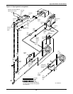
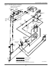
An expansion tank must be provided for expansion and contraction of the fluid due to temperature
change in this closed system. Vents are required at system high points to vent trapped air when fill-
ing the system. A relief valve is a also a necessary piping component.
Depending on the complexity of the system, various other devices may be specified. Pressure gauges,
flow switches, automatic air separator, tempering valves, standby pumps, sensors for electrical con-
trols, and flow switches are just a few of these devices.
NOTICE
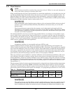
Immediately following the use of water for leak testing or system cleaning, charge the tested
system with the proper percentage of glycol and water for the application’s coldest design
ambient. Complete system drain-down cannot be assured, and equipment damage could
result from freezing of residual water.
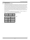
Table 11 Room dew point temperatures
Dry Bulb
°F (°C)
Wet Bulb
°F (°C)
Relative
Humidity
Dew Point*
°F (°C)
70 (21.1)
70 (21.1)
57.2 (14.0)
58.5 (14.7)
45
50
48.0 (8.9)
50.5 (10.3)
72 (22.2)
72 (22.2)
58.9 (24.9)
60.0 (15.5)
45
50
50.0 (10.0)
52.4 (11.3)
75 (23.8)
75 (23.8)
61.2 (16.2)
62.5 (16.9)
45
50
52.4 (11.3)
55.0 (12.7)
* Minimum glycol temperature before condensation will occur.


